Convert 1.5V AA device (Braun Face) to 3.7V 18650 rechargeable

Audioguru again

Joined Oct 21, 2019
6,826
An ordinary rechargeable Lithium battery cell is 4.2V when fully charged and is 3.7V (its half-discharged nominal voltage). The motor will run much faster at 4.2V instead of at 3.7V.
A LiFeP04 battery cell has voltages that are about 0.5V less than an ordinary Lithium battery cell.
 

Ramussons

Joined May 3, 2013
1,572
I need some help with the forward and reverse operation of the motor.
Originally the Braun had a custom design switch built into the main body of the product (I cannot use this) which facilitated polarity reversal with an OFF position in between.
I thought to use a DPDT switch and I placed an order for the following.
View attachment 339984View attachment 339985

Even though they are quite small, I fear that they might still be too big to fit on the surface of the 3cm diameter PVC I am using to extend the flashlight head.

View attachment 339987
As a backup solution, I am thinking of using a DPDT relay (installed inside the tube) with a much smaller latching switch, as a trigger, that can even be installed inside the pipe, with only the push pin protruding.
View attachment 339989
I am worried though, that since there is no OFF position between the states of the relay (forward and reverse currents are immediate), this may lead to motor damage (Is my concern baseless?).

Is there an easy and minimalistic way to get a DPDT to pause (even for half a second) between states?
You can get a DP3T switch with the overall dimensions the same except for a larger length. Maybe this will meet your requirement.
 

Thread Starter

conandrum

Joined Mar 10, 2024
108
...
As for the battery, I found a datasheet for model INR18650. Apparently there is a cut-off circuit set to 2.5V. However, I couldn't find the datasheet for the "Vastfire" brand in your photo. As with all Chinese electronics, don't assume they are telling the truth just because it's printed on the side of the battery. Try discharging the battery in a metal tray. If it cuts off at 2.5V then it's probably in there.
...
I have discharged the battery using an OPUS BT-C3100 for almost 2 hours at 0.5A until it stopped discharging at 2.80V exactly.
This seems to verify the aliexpress shopper's comments where he said that the flashlight stopped working at 2.8V.
I guess this is proof of over-discharge protection by the battery itself... right guys?
Also I then proceeded to charge it at 0.5A and in 3 hours it collected 1247mAh which is on par with specs.
 
Last edited:
I have discharged the battery using an OPUS BT-C3100 for almost 2 hours at 0.5A until it stopped discharging at 2.80V exactly.
This seems to verify the aliexpress shopper's comments where he said that the flashlight stopped working at 2.8V.
I guess this is proof of over-discharge protection by the battery itself... right guys?
I would do 5 or 10 tests at different discharge currents just to be safe. It would be a shame to have it catch fire in your hand!
 

Thread Starter

conandrum

Joined Mar 10, 2024
108
I would do 5 or 10 tests at different discharge currents just to be safe. It would be a shame to have it catch fire in your hand!
I am now doing a discharge refresh cycle at 1A (Discharge and charge the battery 3 times. ). I will update you.
UPDATE: I checked online and saw this: " I see that the 3100 v2.2 discharges the batteries down to 2.8 volts. ". It seems that 2.8V is a feature of this charger. I have to discharge it via other means to check its own protection.

I'd use a switch with an off position. The buck converter is likely to be very sensitive to fault conditions like reverse currents. Also don't switch directions until the motor stops spinning as it will act as a generator for a short time.

I didn't realize you wanted to go in reverse. I'll see if I can come up with a better solution.
Have you had a chance to think about a better solution?
 
Last edited:
I am now doing a discharge refresh cycle at 1A (Discharge and charge the battery 3 times. ). I will update you.
UPDATE: I checked online and saw this: " I see that the 3100 v2.2 discharges the batteries down to 2.8 volts. ". It seems that 2.8V is a feature of this charger. I have to discharge it via other means to check its own protection.


Have you had a chance to think about a better solution?
Good thing you found that information.

And no, looks like a switch with an off position is the only thing that'll fit.
 

DC_Kid

Joined Feb 25, 2008
1,242
haven't had a chance to go purchase one yet. I am sure it will work, but as you said, it will be wasting energy just like the diodes.
I will test it though when I get a chance.
The only way to eliminate waste, and have it reversing, is PWM with H bridge. Finding this as readily available in a tiny package that works for you may be extremely hard to find. If you get help here on AAC to build a ckt in Kicad or the like you could perhaps build something yourself.
 
The only way to eliminate waste, and have it reversing, is PWM with H bridge. Finding this as readily available in a tiny package that works for you may be extremely hard to find. If you get help here on AAC to build a ckt in Kicad or the like you could perhaps build something yourself.
A buck converter is a PWM device with feedback. Without feedback, the voltage will drop in direct proportion to the battery voltage.

Also, why does he need an H bridge? A DPDT ON-OFF-ON switch does the same job.
 
Last edited:

wraujr

Joined Jun 28, 2022
265
Maybe I missed this, but looking at the pictures of the flashlight control board, I see a MOSFET X14 (AO3401) driving the LED with a 150 ohm resistor. The AO3401 is rated for 3A at room temp and you have the 150 ohm resistor you could tweak. Have you tried connecting the motor to the LED wires. You might have to lower the 150 ohms and the controller may be using PWM to adjust the LED intensity, but your motor be OK with it. A scope trace would help determine if PWM in use. You wouldn't have reverse, but don't see why you need reverse....
 

DC_Kid

Joined Feb 25, 2008
1,242
A buck converter is a PWM device with feedback. Without feedback, the voltage will drop in direct proportion to the battery voltage.

Also, why does he need an H bridge? A DPDT ON-OFF-ON switch does the same job.
Don't really need all the parts of a buck to change voltage, can use just a 555 as PWM driver to drive gate of a fet, as example. There are IC's that you can set PWM with resistor with builtin final fet drive. With small % PWM you can drive the motor with higher volts of the batt, no need to change the volts, etc.

Yes, DPDT will work, which is a mechanical H bridge.

OR, skip all the buck or other, just inline a resistor to burn off some power. Direct PWM is most efficient way, but I don't think efficiency is the key thing in this remake adaptation.
 

Thread Starter

conandrum

Joined Mar 10, 2024
108
Flashlight drivers are small. This one is 17 mm diameter; it has a bunch of 350 mA constant current drivers in parallel. The best thing would be to remove all those and replace them with a power MOSFET, since I can't be sure what would happen if it drove a motor instead of an LED, and I'm not willing to test that. Drivers with an ATtiny can be re-flashed with different firmware; there's examples linked on the Budget Light Forum.
http://kaidomain.com/Nanjg-105C-17mm-AMC7135-380mA-4-Groups-Modes-Flashlight-Driver-Board
Maybe I missed this, but looking at the pictures of the flashlight control board, I see a MOSFET X14 (AO3401) driving the LED with a 150 ohm resistor. The AO3401 is rated for 3A at room temp and you have the 150 ohm resistor you could tweak. Have you tried connecting the motor to the LED wires. You might have to lower the 150 ohms and the controller may be using PWM to adjust the LED intensity, but your motor be OK with it. A scope trace would help determine if PWM in use. You wouldn't have reverse, but don't see why you need reverse....
I just did some tests on the current LED driver PCB to see if it will be able to handle powering the motor.
Please remember, that the driver's output will be fed into the buck converter (when I receive it) and the buck will in turn connect to the motor.

Convert 1.5V AA device (Braun Face) to 3.7V 18650 (LED DRIVER TEST#1)

LED:
High mode: 3.3V @ 0.9A (2.97W)
Low Mode: 2.8V @ 0.3A (0.84W)

Motor: no attachement
High mode: 3.6V @ 0.6A (2.16W)
Low Mode: 0.9V @ 0.3A (0.27W)

Convert 1.5V AA device (Braun Face) to 3.7V 18650 (LED DRIVER TEST#2)

Motor: with attachement
High mode: 3.0V @ 1.9A (5.7W)
Low Mode: 0.0V @ 0.0A (0W)

Motor: with attachement & load
High mode: 2.5V @ 2.5A (6.25W)
Low Mode: 0.0V @ 0.0A (0W)

So it looks like this driver was designed to work at a constant 3W load.
3W is also the maximum recommended power as per my communication with the manufacturer:
"I think that 1,5VXmax. 2A (3W) input power is still ok for the FF180PH-3730 motor in my opinion (no Mabuchi statement)."

I am guessing that when I connect the 1.5V buck converter, the driver will be comfortable pushing out up to 3W constant.
As in previous diode test here, realistically I will be pulling between 0.4A to 1.2A max (with the motor attachment).
That's between 0.6W and 1.8W max, easily below the 3W that the driver is capable of supplying.

Are my assumptions correct do you think?
 
Last edited:

Thread Starter

conandrum

Joined Mar 10, 2024
108
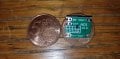
Buck Converter has arrived.

Convert 1.5V AA device (Braun Face) to 3.7V 18650 (1.5V 2A Buck Converter TEST)

Unfortunately the test was disappointing.
The motor will turn if the attachment is not connected.
With the attachment, the motor will not turn. If I give the attachment a spin with my hand, then it will turn.
The attachment will keep turning whilst the amperage is below ~2A in most cases.

The buck converter has the perfect shape and size for my application but not enough power handling.
Let me know what you think.
 

Attachments

Top