It looks like there was some confusion on both our parts about this project. In your most recent video, the buck is fed by an "led driver". I don't know why the driver is even there and wasn't part of my advice.
Here's what I thought the problem was:
1) You have a device that runs on a 1.5V alkaline battery that you wanted to retrofit for a Li-ion battery. The goal was to increase device runtime.
2) You did a bunch of tests (simple observations really) and roughly concluded the motor draws 1-2A at 1.5V.
3) We sized a buck converter to meet this requirement.
The circuit was planned to be: 3.7V Li-ion battery -> Buck converter -> DPDT ON-OFF-ON Switch -> Motor.
So, I'm not sure how the led driver got involved and why you thought it was necessary. I think part of the current problem is you got advice from many people and almost no one kept track of what was actually going on.
This happens a lot with forums where most people give quick answers and very few follow through until the problem is finally solved. I suspect you are also quick to move onto the next thing before fully investigating what is in front of you. I can tell this is partially the case because you are already onto "micro transformers"...
Ok, so now what? This is what I propose:
a) List the components that were in the original device.
b) Determine how the motor was being driven in the original device. Is it powered directly from the battery or is there a bunch of circuitry that you don't understand?
c) If the motor is driven by the battery directly, determine the mix-max current draw under different load conditions (no load to a fully loaded). Start with a bench power supply set to 1.5V. The point of using a bench power supply to obtain current figures is because a battery's voltage will sag under heavy load.
d) Test the buck converter you bought to confirm it actually performs as advertised. Power it directly from the Li-ion battery that you'll be using.
Ah. I was going to suggest using a Nimh cell instead of Lithium, but see you've been doing that. Couldn't you simply keep the Nimh and add a charging plug or socket to the Braun?
It looks like there was some confusion on both our parts about this project. In your most recent video, the buck is fed by an "led driver". I don't know why the driver is even there and wasn't part of my advice.
I left the driver in there in order to
1. keep the button that switches on the device
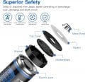
2. keep the USB-C socket and mechanism that charges the 18650 battery while inside the housing
3. keep the mechanism that stops discharge when voltage gets low
The original device is very very simple.
The motor you have already seen in previous photos and videos.
Each pole connected to an AA battery via a windmill type mechanical switch (looks like a 4 leaf clover) responsible for polarity change.
b) Determine how the motor was being driven in the original device. Is it powered directly from the battery or is there a bunch of circuitry that you don't understand?
c) If the motor is driven by the battery directly, determine the mix-max current draw under different load conditions (no load to a fully loaded). Start with a bench power supply set to 1.5V. The point of using a bench power supply to obtain current figures is because a battery's voltage will sag under heavy load.
Ah. I was going to suggest using a Nimh cell instead of Lithium, but see you've been doing that. Couldn't you simply keep the Nimh and add a charging plug or socket to the Braun?
Convert 1.5V AA device (Braun Face) to 3.7V 18650 (1.5V 2A Buck Converter TEST#2)
Testing without the flashlight driver - buck only!
Results are unfortunately the same as in the previous test.
ie. there is not enough power it seems to get the motor turning initially.
With a little manual push, it gets started, but can stall and humm if enough resistance is encountered.
Convert 1.5V AA device (Braun Face) to 3.7V 18650 (1.2V AA NIMH TEST#1)
Here I tested only with a 1.2V AA NIMH battery for amperage.
The battery is at 1.3V and when running the tests drops to 1.0V.
Unfortunately no power supply available, so this test may not be very useful.
(NOTE: my amp meter shows -0.6 when no current flows)
I saw peak currents at startup of
1.79+0.6=2.39A (@1.0V)
Continuous
1.5+0.6=2.1A (@1.0V)
Convert 1.5V AA device (Braun Face) to 3.7V 18650 (1.2V AA NIMH TEST#1)
Here I tested only with a 1.2V AA NIMH battery for amperage.
The battery is at 1.3V and when running the tests drops to 1.0V.
Unfortunately no power supply available, so this test may not be very useful.
(NOTE: my amp meter shows -0.6 when no current flows)
I saw peak currents at startup of
1.79+0.6=2.39A (@1.0V)
Continuous
1.5+0.6=2.1A (@1.0V)
These results are a bummer. They are also on the low end because the buck outputs 1.5V not 1V. The actual current will be closer to 3A peak if not more when driven by 1.5V.
I sort of seen this coming which is why I suggested a buck with 2A continuous and 3A peak. I also tried to get you to measure the current using a voltage source similar to what the buck will output.
The good news is you didn't spend much on the part you bought. It's still a hard lesson but my hope is you learned to think things through a bit more and not jump ahead (for example, spend more time troubleshooting). This project sounds pretty easy but as you've seen, there is a lot that can go wrong.
Bummer for sure.
I wish there was a 3A peak buck in the size required but there was none I could find.
Anything available would have to be installed length-wise taking up a lot of space inside the tube, rendering the final product close to a foot long. That's not practical.
1. I thought of stripping a XTAR AA rechargeable battery off its buck converter, but it looks like it is only capable of 2A output. I may order one to test if it can actually start the motor with the attachment attached. If it can, then I may just dismantle it and use the converter inside it. Unfortunately I have to order it online and wait.
2. Some electronics expert in this forum could maybe design an appropriate buck 17x17mm square (or 24mm diameter disc) and I could get it built.
3. Easy way out is to use a 1.4 Ohm resistor (per DC_Kid) or the 3 diodes I already have. That has been tested and working fine. Problem is that half the battery will be wasted.
4. Alec_t is suggesting I convert the original device and make THAT rechargeable. However, I cannot find a mini USB-C charging board for 1.2V NIMH batteries.
5. Do micro-transformers exist that can convert 4V into 1.5V?
Yes, other members have already suggested similar batteries.
I am more interested in a solution that does not involve removing the batteries to charge them.
I am already doing that as it is, even though I use a separate charger.
Thanks for suggesting it.
Not possible in original housing. https://www.aliexpress.com/w/wholesale-usb-type-c-socket.html
Installing such a socket on the housing requires some space.
It might be possible only by extending the bottom part where the battey compartment opening is and adding the socket there.
The socket will have to carry power via a thin cable to the USB-C socket on the battery.
Even so, I do not think there is enough room inside the battery compartment for the USB-C plug going into the battery.
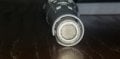
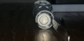
Photos of battery entering the battery chamber from the bottom opening.
The device opening is 16.5mm while my AA is 14.23mm leaving only 2.27mm. I think that disqualifies adding anything to the USB socket before the battery enters the chamber.
However, it could be possible to plug something into the battery if it is already inserted but that would be messy, requiring a huge hole on the side of the chamber.
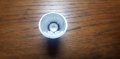
Photo of battery as it rests inside battery chamber (looking from the top down, from where the motor assembly usually sits).
Another option, just connecting a male to a female USB-C plug, where the male plugs into the battery and the female protrudes out of the battery compartment (to accept your power cable), would probably not be flush with the casing.
I do not think there is enough room in the original casing for this mod.
I think the new casing has a lot going for it. It just needs a voltage conversion.
Everything else is already there, including increased capacity/runtime.
These results are a bummer. They are also on the low end because the buck outputs 1.5V not 1V. The actual current will be closer to 3A peak if not more when driven by 1.5V.
I sort of seen this coming which is why I suggested a buck with 2A continuous and 3A peak. I also tried to get you to measure the current using a voltage source similar to what the buck will output.
Crazy idea....
What would happen if I connected 2x buck converters to the battery and joined their output going into the motor?
Would that do any good ?
Crazy idea....
What would happen if I connected 2x buck converters to the battery and joined their output going into the motor?
Would that do any good ?
A dc-dc converter maintains a stable voltage by monitoring a feedback loop (under-voltage -> increase duty cycle and over-voltage -> decrease duty cycle).
If two converters are wired in parallel, the feedback loops will likely fight each other because they don't know what the other loop is compensating for. This will lead to short circuits between the power leads or one of converters doing all the work while the other does nothing.
I can see situations where it is doable but would require the converters to be synchronized.
Have you considered wiring a buck converter dead bug style? Without a PCB there might be enough room.
Maybe make a new topic stating your exact requirements and space allotment for a buck converter. Then the pros can help you find an optimal solution. My knowledge of power converters is mostly theoretical so I'm reluctant to suggest specific components.

 Facebook
 Google
 GitHub
 Linkedin





 ?
?



