Convert 1.5V AA device (Braun Face) to 3.7V 18650 rechargeable

Thread Starter

conandrum

Joined Mar 10, 2024
108
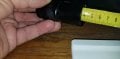
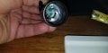
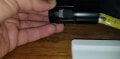
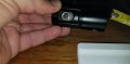
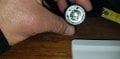
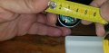
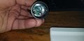
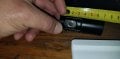
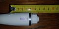
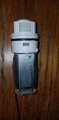
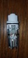
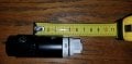
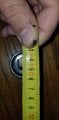
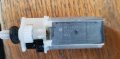
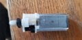
Here are some photos and measurements.
There seems to be 4cm of readily available empty space inside the head.
The Braun motor and switch sections require 4.5cm (I may need to extend the alum tube a bit with PVC maybe)
The only dissapointment is that the product page mentioned 3cm head diameter and I find only 2.5cm.
EDIT: The head outside diameter is actually 3cm. Head thickness about 1mm. However there is a lip right at the edge in order to hold the lens and reflector, so the effective inner diameter here is ~25mm. I used a stepped drill bit to expand this lip a little in order to get the motor inside the head.
Indeed I may need to use 32mm PVC pipe to house the motor (which seems to be 29mm in diameter - I will not know until I disassemble the Braun).
 

Attachments

Last edited:

bassbindevil

Joined Jan 23, 2014
924
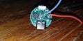
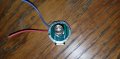
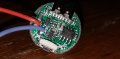
Flashlight drivers are small. This one is 17 mm diameter; it has a bunch of 350 mA constant current drivers in parallel. The best thing would be to remove all those and replace them with a power MOSFET, since I can't be sure what would happen if it drove a motor instead of an LED, and I'm not willing to test that. Drivers with an ATtiny can be re-flashed with different firmware; there's examples linked on the Budget Light Forum.
http://kaidomain.com/Nanjg-105C-17mm-AMC7135-380mA-4-Groups-Modes-Flashlight-Driver-Board
 

Thread Starter

conandrum

Joined Mar 10, 2024
108
Thanks to all offering their input.
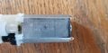
Here is the Braun motor finally.
No identifying markings can be seen yet. I measured resistance 2.5 Ohm.
Seems like there is not enough room to house it completely - Needs 11mm more.
PVC pipe is needed to provide the extra length - plus whatever extra electronic components needed.
 

Attachments

Thread Starter

conandrum

Joined Mar 10, 2024
108
Flashlight drivers are small. This one is 17 mm diameter; it has a bunch of 350 mA constant current drivers in parallel. The best thing would be to remove all those and replace them with a power MOSFET, since I can't be sure what would happen if it drove a motor instead of an LED, and I'm not willing to test that. Drivers with an ATtiny can be re-flashed with different firmware; there's examples linked on the Budget Light Forum.
http://kaidomain.com/Nanjg-105C-17mm-AMC7135-380mA-4-Groups-Modes-Flashlight-Driver-Board
I tested it. Check vid below.
Basically, I noticed that the switch has 2 modes it looks like - full power and reduced power.
In the video, at full power, the motor rotates fast and at reduced power, much slower.
With the attachment though, at full power, the attachment rotates fast and at reduced power, it humms without turning.
You can see the current drawn without attachment is 2A instantaneous and 1A continuous.
With attachment is 2.75A instantaneous and 1.65A continuous.
If it starts pulling hair it will increase slightly I guess.


Thoughts?
 
Last edited:

Thread Starter

conandrum

Joined Mar 10, 2024
108
Convert 1.5V AA device (Braun Face) to 3.7V 18650 rechargeable (Volts test#1)

Without attachment:
Pulls, 3.7V (on high) and 1.26V (on low).

With attachment:
Pulls, on high, 3.24V (no load) and 2.6V (under load).

Convert 1.5V AA device (Braun Face) to 3.7V 18650 rechargeable (Amps test#2)

With attachment:
Pulls, on high, 1.67A (no load) and 2.6A (under load). *Starting current 2.5A*
At 2.7A the red light comes on (possibly overload protection?).

Judging by these numbers,
with attachment, on high, without a load, power used is 5.4W.
with attachment, on high, with a load, power used is 6.8W.
At 7W we get overload red light coming on.

EDIT:
A review on Aliexpress mentioned that " When the light is turned on the button is green, when the voltage drops to 3 V, it starts to flash red, up to 2.8 V the lamp turns off. ". I did not notice a red light when the voltage dropped to 2.6V under load.
 
Last edited:

Thread Starter

conandrum

Joined Mar 10, 2024
108
Testing with an AA HR6 1.2V LADDA 2450mah rechargeable battery

Convert 1.5V AA device (Braun Face) to 3.7V 18650 rechargeable (Volts test#3 1.2V battery)

With attachment:
Pulls, 1.21V (no load) and 1.0V (under load).

Convert 1.5V AA device (Braun Face) to 3.7V 18650 rechargeable (Amps test#4 1.2V battery)

With attachment:
Pulls, 0.13A (no load) and 1.0A (under load).

Judging by these numbers,
with attachment, without a load, power used is 0.15W.
with attachment, with a load, power used is 1.0W.

I think I am done with testing. If you want me to test something let me know.

I have some questions for you.
1. How can I know for sure whether this motor is able to sustain 5.5-6.5W for say 5 minutes usage at a time.
2. If I need to change the motor, what specs should I be looking for? (3.7V 7W RPM? TORQUE? others?)
3. Would you use a buck converter or a new motor?


EDIT:
Using crude strobe light measurement I think the RPM of the attachment is 2600 using the AA 1.2V battery. I will dismantle the gears tomorrow and check for markings and real RPM.
 
Last edited:

Art Vandelay

Joined Nov 1, 2024
140
A buck converter sounds like the way to go. Dropping the voltage with a linear regulator like LM317 will generate a ton of heat and drain the battery even with a heatsink.

As for choosing a buck, there a variety to choose from. Power converters aren't my bag so take this as general advice.

After a bit of research I found TPS62130 that could work. It's a small QFN package which can be hand soldered. Vin = 3-17V, Vout = 0.9-6V, Iout = 3A. Every buck that I know of requires external components like filter capacitors, an inductor and programming resistors. With some luck, you could cram it all into the space you have available. The tough part will be soldering the tiny package.

For the over discharge protection, you will be hard pressed for leftover room but there are a number of ways to implement the function. The most obvious is to use a battery with protection built in.

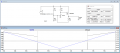
Second to that, here's a comparator circuit that uses TL431 and FDN304P to cut off the battery when it reaches 3.2V. It won't turn back on until the battery is at least 3.4V. The circuit is meant to serve as a basic example and I doubt you'll have space for it. I can't offer much more assistance than this. Good luck.

1.png
 

Thread Starter

conandrum

Joined Mar 10, 2024
108
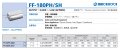
The motor is: FF-180PH-3730 LD565589 ( MABUCHI MOTOR probably)

Specification (from aliexpress):
1. Brand: MABUCHI MOTOR
2. Model: FF-180PH-3730
3. Motor size: 20.2mm*15.4mm
4. Motor height: 32mm
5.Output shaft diameter: 2mm (the end is a knurled shaft)
6.Output shaft length: 8.6mm (include step height)
7. Weight: 32g
8.Voltage Range: DC 2.4V-4.2V
9. Test data:
Voltage: 2.4V No-load Speed: 13800RPM Current: 350mA
Voltage: 3.0V No-load Speed: 17000RPM Current: 390mA
Voltage: 3.7V No-load Speed: 20200RPM Current: 490mA
Voltage: 4.2V No-load Speed: 22500RPM Current: 550mA

Looks like this motor can handle the 18650 battery right?
What do you think?

UPDATE:
Mabuchi Motor Designations and Their Meanings
Looks like the FF-180PH-3730 motor uses 0.3mm diameter of magnet wire with 730 turns.
Since I could not find the PDF for this motor, we can compare with the FF-180PH-2852 (0.2mm 852 windings) below.
It looks like this smaller brother can handle up to 4.5A before stalling and a max of 5.6W.
The bigger FF-180PH-3730 should be able to handle more than this surely.
2025-01-01_22-02-26.jpg
 

Attachments

Last edited:

amorawala

Joined Oct 17, 2017
1
Hi all,
I need your ideas again.
I am trying to convert a trusty 8 year-old device (Braun Face) from an AA battery into a rechargeable. (they make rechargeable versions of this now).
(It is too much hassle opening and closing the battery compartment on these. You need a coin to twist the base. So even using a rechargeable AA battery requires you to open the compartment and recharge the battery every 1 or 2 uses)

I found a rechargeable flashlight on Ali with the right dimensions (3cm head) to accept the Braun motor and tip.
Also I chose this UV flashlight because it has only ON/OFF switch functionality (no SOS etc).
The switch will make it simpe to use, but the BRAUN switch will still be needed for forward and reverse rotation of the head.
https://www.aliexpress.com/item/1005005791680770.html
View attachment 338984View attachment 338985

When I receive it next week, I will begin the process of tranfering the motor by first removing the lense and UV LED.

The obvious problem now is Voltage - 1.5V to 3.7V.
I already tried running the motor with a 18650 and it works fine, but rotates at the speed of light LOL

MY IDEA :
I thought I could use a small potentiometer in series with the motor and regulate the speed of the motor, before hiding it, under the motor, inside the flashlight head.
I suppose I should use a potentiometer that can handle the wattage of the motor (I do not know how many watts until I see the model no. or measure the current it pulls under some load).

Do you have some better idea?
I have a similar issue hacking a Philips 1.2 V shaver to operate on Li ion cell. I am planning to have the power module external. A very small circuit with LM 1117 1.8 vdc with Li ion voltage as input. The whole miniature circuit will be hanging from the fingers by a threaded loop, while the shaver will be held in the hand.
 

Doktor Jones

Joined Oct 5, 2011
75
The motor is: FF-180PH-3730 LD565589 ( MABUCHI MOTOR probably)

Specification (from aliexpress):
1. Brand: MABUCHI MOTOR
2. Model: FF-180PH-3730
3. Motor size: 20.2mm*15.4mm
4. Motor height: 32mm
5.Output shaft diameter: 2mm (the end is a knurled shaft)
6.Output shaft length: 8.6mm (include step height)
7. Weight: 32g
8.Voltage Range: DC 2.4V-4.2V
9. Test data:
Voltage: 2.4V No-load Speed: 13800RPM Current: 350mA
Voltage: 3.0V No-load Speed: 17000RPM Current: 390mA
Voltage: 3.7V No-load Speed: 20200RPM Current: 490mA
Voltage: 4.2V No-load Speed: 22500RPM Current: 550mA

Looks like this motor can handle the 18650 battery right?
What do you think?

UPDATE:
Mabuchi Motor Designations and Their Meanings
Looks like the FF-180PH-3730 motor uses 0.3mm diameter of magnet wire with 730 turns.
Since I could not find the PDF for this motor, we can compare with the FF-180PH-2852 (0.2mm 852 windings) below.
It looks like this smaller brother can handle up to 4.5A before stalling and a max of 5.6W.
The bigger FF-180PH-3730 should be able to handle more than this surely.
View attachment 339400
Given the specs we're seeing, I feel like a simple diode drop would be sufficient to protect the motor and limit its top speed. Something like a BY550-400 should be beefy enough to handle the current draw of the motor and keep the operating voltage below 4V even on a fully charged battery.

Obviously it's not active regulation, so you'll see the speed drop as the battery voltage drops, but it's a single component so you're not trying to stuff a whole PCB (or dead bug circuit :X) in there, and can maybe squeak by with a less substantial extension of the (former) flashlight's body?
 

Thread Starter

conandrum

Joined Mar 10, 2024
108
Given the specs we're seeing, I feel like a simple diode drop would be sufficient to protect the motor and limit its top speed. Something like a BY550-400 should be beefy enough to handle the current draw of the motor and keep the operating voltage below 4V even on a fully charged battery.

Obviously it's not active regulation, so you'll see the speed drop as the battery voltage drops, but it's a single component so you're not trying to stuff a whole PCB (or dead bug circuit :X) in there, and can maybe squeak by with a less substantial extension of the (former) flashlight's body?
Yes, I am waiting confirmation from Mabuchi Motor (Europe) GmbH, regarding the operating parameters of this particular motor. I think by tomorrow I should have an answer.
If they confirm the motor can handle up to 4.2V@5.6W then I have already bought 4x BZW06-10 diodes to try.
If you have a zener solution, please suggest a model number (I think zeners should be acompanied by a resistor).
 
Last edited:

DC_Kid

Joined Feb 25, 2008
1,242
If they confirm the motor can handle up to 4.2V@5.6W then I have already bought 4x BZW06-10 diodes to try.
Just a tidbit of info that may help.
I have many times over-driven LED's using PWM in very low % duty cycle.
Most of the stuff you can power up can withstand much higher voltage in context of dielectric ability, you just can't run it too long because it gets too hot and melts.

You can run a 4v motor using 12v as long as the PWM is done right.

So, you can implement a PWM drive using 3.7v Li batt to power a 1.5v motor.
As long as the motor wire is insulated enough to keep 3.7v from shorting through, it should work.

Perhaps something to test. It would make things very simple.
 

Thread Starter

conandrum

Joined Mar 10, 2024
108
This is the email I received from Mabuchi Motor (Europe) GmbH regarding the FF180PH-3730 motor.
(it looks like the aliexpress motor with the same name is either a fake/copy or is accompanied by erroneous specs)

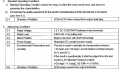
Please find below the specified operating conditions/performance data of your sample motor (production code LD565589) for your reference.

a.png
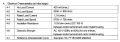
As informed, the FF180PH-3730 can’t be operated at 3,3V because the motor speed would theoretically reach >18.000rpm by far exceeding the capability of motors equipped with metal fork brushes. In case of 3,3V operating voltage, a lower output winding like 2852 or even better 2661/2765 needs to be applied to ensure a safe long-term operation. Either way, the motor output will be significantly lower compared to the (overloaded) FF180PH-3730 at 3,3V.

b.png
Basically, about 1,5W (0,981mNm/1,2Amax x 1,2V) is a realistic and sustainable output for the FF180-motor type/size.
 

Thread Starter

conandrum

Joined Mar 10, 2024
108
DIODES TEST#1
Testing voltage reduction from 3.7V down to 1.4V, using 3x BZW06-10 DIOTEC diodes.
The motor powers up at around 1.2V and quickly rises to a max of 1.45V pulling 0.4A (with the motor attachment but without a load).
Total power consumption 0.58W.
Ambient Temp: 17 Celsius
Diode Max Temp: 34 Celsius


Thread Starter

conandrum

Joined Mar 10, 2024
108
DIODES TEST#2
Load testing after voltage reduction from 3.7V down to 1.4V, using 3x BZW06-10 DIOTEC diodes.
When loading the motor we see current rise from 0.4A (1.45V) to 1.2A (1.16V) (near stall).
A realistic maximum load under normal use would be 0.8A (~1.2V).
Max power consumption 1.392W.
Ambient Temp: 17
Celsius Diode Max Temp (load): 40 Celsius

https://youtube.com/shorts/toVGfq8Ah2I
 
Top