DIODES TEST#3
Testing after voltage reduction from 3.7V down to 1.4V, using 3x BZW06-10 DIOTEC diodes.
Here I tested the power consumption at the battery, and before the diodes.
The motor is with attachment as in the previous two tests.
Without load, we have 3.8V 0.30A (1.14W)
Under load, we have 3.64V 1A (max) (3.64W)
Conclusion:
Without load: 1.14W - 0.58 = 0.56W wasted as heat in diodes
Under max load: 3.64 - 1.392 = 2.25W wasted as heat in diodes
Under normal usage, somewhere between 0.6W and 1.5W will be wasted as heat in the diodes.
That's basically half the battery's energy (or more) as best case scenario.
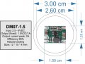
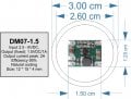
At the time of writting, I think the easiest solution available off the shelf is the following buck converter, which is small enough to fit inside the flashlight head and is as close to the operating parameters supported by the motor.
Do you think that the 1.5V output will be too high? Any objections to this converter? https://www.aliexpress.com/item/1005006096221803.html
If you have another suggestion please let me know.
A buck converter sounds like the way to go. Dropping the voltage with a linear regulator like LM317 will generate a ton of heat and drain the battery even with a heatsink.
...
After a bit of research I found TPS62130 that could work. It's a small QFN package which can be hand soldered. Vin = 3-17V, Vout = 0.9-6V, Iout = 3A.
For the over discharge protection, you will be hard pressed for leftover room but there are a number of ways to implement the function. The most obvious is to use a battery with protection built in.
I plan to use the flashlight PCB output as input to the buck converter.
In the aliexpress user reviews I found this: " . When the light is turned on the button is green, when the voltage drops to 3 V, it starts to flash red, up to 2.8 V the lamp turns off."
I am not sure if this functionality is due to the PCB or due to the battery having protection.
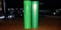
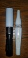
Here is a few photos of the cell that came with the flashlight (left) next to a Samsung cell that was in my Makita battery (right).
Label mentions there is discharge protection. (Label has also quite a few spelling mistakes and new English words LOL)
TI TL594 and a smd fet.
or
soic 555 and a smd fet.
or
small dc-dc converter IC package (no extra parts needed).
It would need minimal count on external components.
If you need a COTS item it may be hard to find. If you will design the PCB and have it made by Sierra, LJCPCB, PCBWay, etc, then you can make something very tiny that fits.
Much appreciated but since I am not an electrical engineer, it would be difficult for me to source and design an appropriate circuit. I could build it if I had the design ready.
But even then, something off the shelf is much easier for myself and everyone that might want to follow in my footsteps.
So I would like to ask you, what do you think of the buck converter I posted earlier?
At the time of writting, I think the easiest solution available off the shelf is the following buck converter, which is small enough to fit inside the flashlight head and is as close to the operating parameters supported by the motor.
Do you think that the 1.5V output will be too high? Any objections to this converter? View attachment 339765 https://www.aliexpress.com/item/1005006096221803.html
If you have another suggestion please let me know.
The output voltage looks good but I'm wary about the current. In a post you said:
"You can see the current drawn without attachment is 2A instantaneous and 1A continuous.
With attachment is 2.75A instantaneous and 1.65A continuous.
If it starts pulling hair it will increase slightly I guess."
Assuming you used a 1.5V bench supply to obtain these figures, the buck you selected probably won't keep up. I'd try to find one with at least 2A continuous and 3A peak. It's always a good idea to include a decent safety margin.
As for the battery, I found a datasheet for model INR18650. Apparently there is a cut-off circuit set to 2.5V. However, I couldn't find the datasheet for the "Vastfire" brand in your photo. As with all Chinese electronics, don't assume they are telling the truth just because it's printed on the side of the battery. Try discharging the battery in a metal tray. If it cuts off at 2.5V then it's probably in there.
The output voltage looks good but I'm wary about the current. In a post you said:
"You can see the current drawn without attachment is 2A instantaneous and 1A continuous.
With attachment is 2.75A instantaneous and 1.65A continuous.
If it starts pulling hair it will increase slightly I guess."
Those measurements were taken when powering the motor straight from the 18650.
I have more indicative tests. One using the ladda 1.2v rechargeable battery, should be a couple of posts further down on that page. A second test was posted yesterday at 1.4v going through 3 diodes. Amperage at these voltages should be less than 1a under normal usage.
Regarding low voltage protection, I am not worried about atm. Worst case I will go buy a proper battery with protection.
Please find below the official PC for the FF180PH-3730.
Yes, I think that 1,5VXmax. 2A (3W) input power is still ok for the FF180PH-3730 motor in my opinion (no Mabuchi statement).
However, the resulting motor output power will be about 1,5W depending on the operating point (about 50%).
To judge the motor operating point efficiency and life expectancy accurately , you need to record both current and speed under load during motor testing.
Based on the above and without a quick alternative solution, I will place my order today.
I will now turn my attention to the PVC head extension.
I will update as I progress.
Hi all,
I need your ideas again.
I am trying to convert a trusty 8 year-old device (Braun Face) from an AA battery into a rechargeable. (they make rechargeable versions of this now).
(It is too much hassle opening and closing the battery compartment on these. You need a coin to twist the base. So even using a rechargeable AA battery requires you to open the compartment and recharge the battery every 1 or 2 uses)
I found a rechargeable flashlight on Ali with the right dimensions (3cm head) to accept the Braun motor and tip.
Also I chose this UV flashlight because it has only ON/OFF switch functionality (no SOS etc).
The switch will make it simpe to use, but the BRAUN switch will still be needed for forward and reverse rotation of the head. https://www.aliexpress.com/item/1005005791680770.html View attachment 338984View attachment 338985
When I receive it next week, I will begin the process of tranfering the motor by first removing the lense and UV LED.
The obvious problem now is Voltage - 1.5V to 3.7V.
I already tried running the motor with a 18650 and it works fine, but rotates at the speed of light LOL
MY IDEA :
I thought I could use a small potentiometer in series with the motor and regulate the speed of the motor, before hiding it, under the motor, inside the flashlight head.
I suppose I should use a potentiometer that can handle the wattage of the motor (I do not know how many watts until I see the model no. or measure the current it pulls under some load).
Thanks for the suggestion but I was already using rechargeable batteries (1.2V x 2450mAh = 2940mWh). I wanted to avoid having to take them out every couple of uses to recharge them. I wanted a plug and play solution and that's why I decided to modify a flashlight with a larger capacity 18650 battery (3.7v x 1200mAh = 4400mWh).
The 750mWh suggested is way too low anyway and I do not think it would last not even for a single run in my use case.
DIODES TEST#3
Testing after voltage reduction from 3.7V down to 1.4V, using 3x BZW06-10 DIOTEC diodes.
Here I tested the power consumption at the battery, and before the diodes.
The motor is with attachment as in the previous two tests.
Without load, we have 3.8V 0.30A (1.14W)
Under load, we have 3.64V 1A (max) (3.64W)
Conclusion:
Without load: 1.14W - 0.58 = 0.56W wasted as heat in diodes
Under max load: 3.64 - 1.392 = 2.25W wasted as heat in diodes
Under normal usage, somewhere between 0.6W and 1.5W will be wasted as heat in the diodes.
That's basically half the battery's energy (or more) as best case scenario.
I ran some tests in LTspice. I did a current control ckt using a nFET (just 3 passive components).
But then just shoved a 1ohm resistor in front of your motor ohms for both no-load and load, ran a batt sweep from 3.8v to 2v.
Instead of diodes just use a single 1ohm resistor inline with your motor. This is as simple as you'll get. Diodes or resistor, same wasted heat, etc.
I need some help with the forward and reverse operation of the motor.
Originally the Braun had a custom design switch built into the main body of the product (I cannot use this) which facilitated polarity reversal with an OFF position in between.
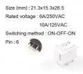
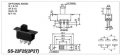
I thought to use a DPDT switch and I placed an order for the following.
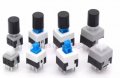
Even though they are quite small, I fear that they might still be too big to fit on the surface of the 3cm diameter PVC I am using to extend the flashlight head.
As a backup solution, I am thinking of using a DPDT relay (installed inside the tube) with a much smaller latching switch, as a trigger, that can even be installed inside the pipe, with only the push pin protruding.
I am worried though, that since there is no OFF position between the states of the relay (forward and reverse currents are immediate), this may lead to motor damage (Is my concern baseless?).
Is there an easy and minimalistic way to get a DPDT to pause (even for half a second) between states?
The cut-off voltage refers to the test conditions for discharge capacity, not a built-in limit. A protected cell would have some cut-off voltage, but in my experience if a "fire" cell has a fictitious capacity, the protection is likely to be fictitious as well. However, 1200 mAh is a realistic capacity for a high-current cell, and it looks a bit taller than the other cell, so maybe it is real.
The cut-off voltage refers to the test conditions for discharge capacity, not a built-in limit. A protected cell would have some cut-off voltage, but in my experience if a "fire" cell has a fictitious capacity, the protection is likely to be fictitious as well. However, 1200 mAh is a realistic capacity for a high-current cell, and it looks a bit taller than the other cell, so maybe it is real.
Yea, I couldn't tell if it has a cut off circuit. Some data sheets for that model don't say anything about a cut off voltage. That's why I suggested doing a discharge test.
I need some help with the forward and reverse operation of the motor.
Originally the Braun had a custom design switch built into the main body of the product (I cannot use this) which facilitated polarity reversal with an OFF position in between.
I thought to use a DPDT switch and I placed an order for the following. View attachment 339984View attachment 339985
Even though they are quite small, I fear that they might still be too big to fit on the surface of the 3cm diameter PVC I am using to extend the flashlight head.
View attachment 339987
As a backup solution, I am thinking of using a DPDT relay (installed inside the tube) with a much smaller latching switch, as a trigger, that can even be installed inside the pipe, with only the push pin protruding. View attachment 339989
I am worried though, that since there is no OFF position between the states of the relay (forward and reverse currents are immediate), this may lead to motor damage (Is my concern baseless?).
Is there an easy and minimalistic way to get a DPDT to pause (even for half a second) between states?
I'd use a switch with an off position. The buck converter is likely to be very sensitive to fault conditions like reverse currents. Also don't switch directions until the motor stops spinning as it will act as a generator for a short time.
I didn't realize you wanted to go in reverse. I'll see if I can come up with a better solution.

 Facebook
 Google
 GitHub
 Linkedin