Convert 1.5V AA device (Braun Face) to 3.7V 18650 rechargeable

Thread Starter

conandrum

Joined Mar 10, 2024
108
If two converters are wired in parallel, the feedback loops will likely fight each other because they don't know what the other loop is compensating for. This will lead to short circuits between the power leads or one of converters doing all the work while the other does nothing.
I can see situations where it is doable but would require the converters to be synchronized.
What if I use a diode on each VOut+ & VOut- of each converter? Would that improve things?
There is more than enough room for 2 such converters.

Have you considered wiring a buck converter dead bug style? Without a PCB there might be enough room.
Maybe make a new topic stating your exact requirements and space allotment for a buck converter. Then the pros can help you find an optimal solution.
I will try that. Thanks Art.
 
What if I use a diode on each VOut+ & VOut- of each converter? Would that improve things?
There is more than enough room for 2 such converters.


I will try that. Thanks Art.
Diodes will logically OR the output voltages not combine the currents.

The only way I know to parallel voltage sources for more current is to ensure the output voltages are the same. Diodes won't help in this case because the bucks need to be synchronized.
 

Thread Starter

conandrum

Joined Mar 10, 2024
108
Diodes will logically OR the output voltages not combine the currents.

The only way I know to parallel voltage sources for more current is to ensure the output voltages are the same. Diodes won't help in this case because the bucks need to be synchronized.
If you happen to know, how do they achive this with solar panels? it can't be too difficult surely.
 

Thread Starter

conandrum

Joined Mar 10, 2024
108
A solar panel behaves more like a current source not a voltage source. Parallel current sources are additive like series voltage sources. Solar panels are sort of in a class of their own.
The past few minutes I did some reading, so forgive me if I am mistaken.
Since my 2 converters are identical, and they do not output pulsed DC, but instead steady DC, that means that there is no need to synchronize Voltage, Frequency or Phase. (voltage already synced at 1.5V)
This page actually says
"It's also worth noting that for best results, the power supplies connected in parallel should be identical. "
https://www.bravoelectro.com/blog/post/connecting-power-supplies-in-series-vs-parallel
What do you say?
 
The past few minutes I did some reading, so forgive me if I am mistaken.
Since my 2 converters are identical, and they do not output pulsed DC, but instead steady DC, that means that there is no need to synchronize Voltage, Frequency or Phase. (voltage already synced at 1.5V)
This page actually says
"It's also worth noting that for best results, the power supplies connected in parallel should be identical. "
https://www.bravoelectro.com/blog/post/connecting-power-supplies-in-series-vs-parallel
What do you say?
That article appears to be talking about Linear power supplies.

A buck converter is a Switched Mode Power Supply meaning it switches a transistor to pulse current into the load.

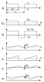
A regular multimeter is too slow to sample the the ripple voltage so it appears as 0Hz DC but actually it's constantly changing. Larger capacitors will reduce the ripple voltage but it's always there. You can confirm this by zooming in with an oscilloscope. Consider this diagram:

Waveform (1).png

This shows the ripple current and ripple voltage at the capacitor (Ic, Vc). Depending on the application, some loads can tolerate a fair amount of ripple such as a motor.

Going back to using two bucks in parallel, the problem boils down to being in phase. Not only do the frequencies have to be the same, but the systems have to start up at the same time to stay in phase for the entire duration of operation.

Therefore, there must be some feedback between the two devices which synchronizes them for this purpose.

Without the shared feedback, one capacitor might be at 10.1V while the other is at 10.2V. There will be 0.1V between the power leads which may not sound like much, but if the output impedance is low enough, large currents could back feed into the other module.

It's hard for me to say exactly what would happen in these situations so I'm going off general theory.

The bottom line is you shouldn't try it unless you are willing to potentially destroy both modules and the load! Unfortunately power converter are highly tuned devices where each component values must be carefully chosen.

https://sciamble.com/resources/pe-drives-lab/basic-pe/buck-converter
 

Thread Starter

conandrum

Joined Mar 10, 2024
108
Did one resistor not work?
Did not have one resistor so I got 2 of them (1Ω+0.4Ω 3W) 1.4Ω total.
Voltage is high, close to 2V across the motor.
Resistors are 3W and are barely warm after this short test.

Convert 1.5V AA device (Braun Face) to 3.7V 18650 (1.4Ω Resistors TEST#1)

This is not an ideal solution (just like the diodes).
I will probably just use diodes since they are much smaller (and 1.4V across motor already), until I manage to get the right buck converter built.
If anyone is capable, you can help me out here: https://forum.allaboutcircuits.com/...o-3-7v-18650-rechargeable.204634/post-1964061
 
Last edited:

Thread Starter

conandrum

Joined Mar 10, 2024
108
The resistor will be labeled, many time that's not what they read on a decent ohm meter.
3W is power rating, tolerance says how much off they can be above or below the stated ohms.
Unfortunately I do not have such info.

Convert 1.5V AA device (Braun Face) to 3.7V 18650 (3.2Ω Resistors TEST#2)

3.2Ω Resistors in this test are rated 2W. The available 5W resistors I found, were too chunky for this application.
The 3x Diodes I eventually used are BZW06-10 (Pd - Power Dissipation: 5 W)
 
Last edited:

Thread Starter

conandrum

Joined Mar 10, 2024
108
Convert 1.5V AA device (Braun Face) to 3.7V 18650 (Assembly)

NOTE: Regarding resistors, see previous post. 3.2Ω Resistors seem to be equivalent to the 3 diodes used.
 

Thread Starter

conandrum

Joined Mar 10, 2024
108
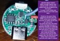
LED DRIVER WEAK POINTS
When enough rotation was placed on the +ve wire, the copper pad was stripped from the board.
To repair, more solder was used to attach to the R150 solid base.
20241230_175759.jpg

However, the same thing happened (at this time the R150 contact was also probably damaged).
Before discovering that the R150 was damaged I drilled a hole where the red wire used to be a epoxied a nail through it to be able to sustain any force.
20250207_002711.jpg
20250207_001646 - Copy.jpg
Unfortunately solder would no longer stick to the R150 due to previous damage. I even managed to repair the R150 so that solder would now stick, and voltage was showing properly, but no current would flow and resistance was quite high.

The R150 may have also been further damaged because of repeated attempts at soldering, since the resistance measured was well above 0.150 Ohm and no current would flow.
This is why the R150 was removed and replaced with copper wire, but now the on/off button does not function correctly and output is always ON.

UPDATE#1:
Within 12 hours the battery was completely drained even though the motor was not running.
This shows that the R150 resistor is essential to the healthy operation of this driver and should be replaced.
UPDATE#2:
No it wasn't the battery that got discharged but rather the driver circuit probably got damaged overnight.
The battery is OK.
 
Last edited:

Thread Starter

conandrum

Joined Mar 10, 2024
108
In the meantime, I am ready to explore the options suggested by Mabuchi here.
ie.
"In case of 3,3V operating voltage, a lower output winding like 2852 or even better 2661/2765 needs to be applied to ensure a safe long-term operation. "
So instead of spending $40+ on custom buck converters, I placed an order for these cheap motors:
MABUCHI FF-180SH-2290 and Mabuchi FF-180SH-2661

I will also try to replace with a new R150 to restore the driver, in case the supplier cannot send me a new pcb.
If all goes well this project will be 100% success and much better than the current Braun offerings.
I will update soon enough.
 

Thread Starter

conandrum

Joined Mar 10, 2024
108
In the meantime, I am ready to explore the options suggested by Mabuchi here.
ie.

So instead of spending $40+ on custom buck converters, I placed an order for these cheap motors:
MABUCHI FF-180SH-2290 and Mabuchi FF-180SH-2661

I will also try to replace with a new R150 to restore the driver, in case the supplier cannot send me a new pcb.
If all goes well this project will be 100% success and much better than the current Braun offerings.
I will update soon enough.
I received my new flashlight and I am ready to rumble again with a few surprises!

Question:
Is it BAD if I connect:
  1. motor +ve to the LED +ve wire and
  2. motor -ve to the battery -ve (thus making the LED -ve wire obsolete)?
I measured the voltage between battery -ve & LED -ve and it is practically 0V.
 
Top