Facebook
 Google
 GitHub
 Linkedin


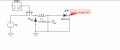
Hello.So I want to build a buck converter on a breadboard.The PWM frequency will be close to 1000Hz and I will be using a 2.2mH inductor.
I want my buck converter to operate in CCM.The target output voltage is 6.5V bcs I want to be able to power a RGB led.I am targeting at a continuous current of 10mA which means ripple current cannot be above 10mA if I want it to run in CCM and preferable 1mA ripple current is the target.
Well the math dont workout.For a 6.5V target output at Vin = 100V at 1000Hz oscillation frequency and a 2.2mH inductor the ripple current is much larger than 10mA let alone 1mA which is the target.Any solutions?
I want my buck converter to operate in CCM.The target output voltage is 6.5V bcs I want to be able to power a RGB led.I am targeting at a continuous current of 10mA which means ripple current cannot be above 10mA if I want it to run in CCM and preferable 1mA ripple current is the target.
Well the math dont workout.For a 6.5V target output at Vin = 100V at 1000Hz oscillation frequency and a 2.2mH inductor the ripple current is much larger than 10mA let alone 1mA which is the target.Any solutions?