Why when I Replace the PCB pot with manual pots, the manual pots wont work when correctly wired

R!f@@

Joined Apr 2, 2009
10,007
OP says the wire glows and sometime craps out.
Now I haven't use any of the sort or cut any foam but could it be that a CC supply is used to source the current constantly via the wire so that it remains at an almost constant temp.
With proper tension it should work.

The CC will force the wire to heat up during heavy cutting and reduce heat when no in use. No ?

How can OP do it, OP is having a hell of a time trying to mod the converter.

What I do not get is the fine pot shorting the post and sky rocketing the output.
That is not possible. clearly OP is not wiring the freekin thing right.
 

R!f@@

Joined Apr 2, 2009
10,007
@Tonyr1084 I am in noway jealous or have any hard feeling towards you when I say that I like to know why OP is bend on your idea ( which I believe is valid for most cases :) ) rather than reading my post and see what OP can do to figure out the issue step by step. o_O

My suggestion includes your idea but OP is not following my suggestion to figure out his problem. :confused:
 

bertus

Joined Apr 5, 2008
22,991
Hello,

I would first try to get it working without the fine tune pot.
If that works, you could post the results and then we cal look how to implement the fine tune pot.

Bertus
 

R!f@@

Joined Apr 2, 2009
10,007
Hello,

I would first try to get it working without the fine tune pot.
If that works, you could post the results and then we cal look how to implement the fine tune pot.

Bertus
Thank you bertus.:)

That's what I said but I do not think OP wants to do that, instead OP wants it to work with all the pots. It is clear OP does not understand the fine pot concept used in PSU's but still have not done and provided end result of said suggestions by other members :oops:
 

Thread Starter

born2dive00

Joined Oct 24, 2016
285
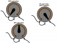
Hello guys; I am taking your suggestions. please read the beginning part of post 16 and 21, part of post 21 got chopped off where I said success. What I did was soldered 90 degree servo pins to where the pots were, I then one pot at a time, connected a servo wire to the old PCB Pot. and the old PCB pot worked with the extensions. I then took off the PCB pot and wired in the Cosmos pots which worked fine exactly the same as the PCB pot.
SO replacing Pot for pot with using an extension, the system works fine.

The problem arrises when I have tried to put in the fine tune pot. Tonys first illustration (which he says is for Current) worked fine with the course and fine tuning on the CV side. normal adjustment from o to 87 volts on course and 0-.9v on the fine.

But he said that Illustration 1 was incorrect. and told me to wire up illustration 2 (which is for voltage.) This is where all hell is breaking loose. there is no adjustment on the fine tune pots with a 5k course 500 ohm fine for the CC, and 200k course and a 2k fine.

I replaced the 2k with a 20k remembering that tony said it might not work well at lower voltages, I removed the 2k and replaced it with a 20k plugged it in and the voltage exceeded the maximum (87v) by nearly 40v. I tried moving all the pots knobs to bring down the voltage to normal, and nothing worked.

I pulled the 500ohm fine CC pot and now the course CV is back in normal range of 0-87v. but still no adjustment in the CV fine pot.
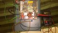
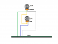
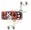
As far not wiring it up correctly. I wired exactly to illustration 2, please see the photos and my diagram of the photo. (I believe that I have wired it up correctly)

So now the question is. so in short. original pcb pots on the board (work) original PCB pots on extension to board (work) new Dial pots (1 course same value as original pcb pots) on extension to board(work)

New Course dial pots on extension to boar + fine tuned pots NO GO with illustration 2


@Tonyr1084 I am in noway jealous or have any hard feeling towards you when I say that I like to know why OP is bend on your idea ( which I believe is valid for most cases :) ) rather than reading my post and see what OP can do to figure out the issue step by step. o_O
My suggestion includes your idea but OP is not following my suggestion to figure out his problem. :confused:
Thank you bertus.:)

That's what I said but I do not think OP wants to do that, instead OP wants it to work with all the pots. It is clear OP does not understand the fine pot concept used in PSU's but still have not done and provided end result of said suggestions by other members :oops:
 

Thread Starter

born2dive00

Joined Oct 24, 2016
285
Short bus, On small foam cutting projects, the Ac systems work fine. up to 4' at 6 ' it starts to get jagged cuts and at 7' or more it looks like someone cut the foam with a chain saw. Because the heating and cooling of the systems and getting hot spots on the wire. This happens when you use AC power over a long wire (I don't understand it but it has been related bouncing a long cable secured on both ends. if you bounce one end one direction say up and down at the same frequency, on the other end it will bounce at a different speed. this difference will will send the wave back to the starting point Where you are bouncing the cable. causing a disruption in the wave. I guess like a harmonic wave in a tuned pipe. As the imbalance tries to cancel out it creates a cold spot on the wire until it stablizes and starts resonating at the correct frequency. The ac in the cutting wire, as long as the wire is short or is stablized, will work fine, as soon as it starts getting long, (as I understand it )this bouncing back and fourth is what causes the hot and cold cycling, and destroys the rhiostats,

If you look at the industrial foam cutters used for 8' and up you will see that (most) are DC and use constant current with large capacitors to I guess stabilize the current. anyway they cut like champs but they are between $2,000 and $60,000 which is way more than what I have to spend

Did you read the link I gave earlier? The one Tony liked? Still don't understand your insistence on this wire cutter using DC, when most of them are using AC, and this is both the store bought and home made hot wire cutters. I'm pretty sure (without knowing it myself) there is a reason behind them using AC on the actual cutting wire.

On second thought maybe I do know why they don't use a switcher power supply. Probably the same reason they don't suggest them for stepper motors. It's the very small output capacitors, compared to a linear type power supply. The larger, much larger output cap in a linear supply gives the output more 'headroom', more available power between the rectified DC pulses. Switchers work great and are good for what they're made for, but there are things they don't work good on.
 
Last edited:

Thread Starter

born2dive00

Joined Oct 24, 2016
285
Tony, do you know of any other way to turn on and off the short protection (if these circuits are short protected) I sure don't. I know it would take a 10w or so resistor at about 500 ohm depending on the current, I never said that the resistors were small.
If you do know of a way of disabling the short protection that can be permanently installed and be turned on and off with this project.
Please share I would love to hear how it is done.

The OP would have to use a very high wattage resistor. Trying to use a 1/4 watt or 1/2 watt, anything under 10 watt may burn up. It all depends on the wire resistance as well.

At a hardware store that was going out of business in Ely Nevada I bought a multi-tapped (doorbell) transformer with a common, 8 VAC, 16 VAC and 24 VAC outputs and I got it for a couple dollars. I have (and posted about this transformer before) a transformer out of a dead stereo. It has three secondary outputs. One at 5 VAC, one at 24 VAC with two multi taps with 12 VAC between them and one center tapped at 65 VAC. I also have several other transformers that came from different projects, so using an old transformer is VERY easy to acquire. I even have a couple micro-wave oven transformers. So any hobbyist would likely have a few (at least) transformers available for experimentation. Light dimmers are cheap enough. If all someone is doing is cutting foam I think this would be the way to go. Heat up the wire just hot enough to cut one inch (thickness) every two seconds and the wire will likely never glow red hot. If it's glowing red hot then it's TOO HOT.

But hey! The OP wants to do it his way - I say "let him."
 

Thread Starter

born2dive00

Joined Oct 24, 2016
285
I am going to back to the beginning on what we know for certain. then I will make posts of each thing I did step by step and report my findings.
Post 1 Findings original setup from the factory, please see photo below

Ok I did some more testing and found out something interesting. maybe significant maybe not.

I looked at the pins again confirmed that both #1 pins on the CC (502 pot) and the CC (204 pot) have power coming in. the CC 5k pot pin 1 has 4.9v. The CV 200k pot pin 1 has 114-120v.

I retested to re confirm that pins 2 and 3 on the CV and CC pots with a continuity tester both pins (2 and 3) on each pot chimed the tester when I touched each one to the ground out terminal.
ie.cv pin 2 to ground buzz,
CV pin 3 to ground buzz,
CC pin 2 to ground buzz,
CC pin 3 to ground buzz.

I then proceeded to test for continuity across the pins on the CV terminals on the board
Pins 1 and 2 did not chime off,
Pins 1 and 3 did not chime off
BUT PIN 2 AND 3 DID CHIME OFF

I proceeded to test for continuity across the pins on the CC terminals of the board
Pins 1 and 2 did not chime off
pins 1 and 3 did not chime off
BUT PINS 2 AND 3 DID CHIME OFF

So with both pins 2 and 3 chiming off to the ground terminal AND the pins 2 and 3 having continuity across them is leading me to conclude (perhaps incorrectly) that both pins 2 and 3 are connected to ground.

Unless someone else has a idea why they are chiming across.
If there was something in the way of the ground, i.e. a diode, a resistor a chip, it would break the connection and not have any continuity or would be high impedance correct and not trip the signal chime off correct?? The multimeter was reading something like .009-.012 (if I recall correctly) and chiming off.

So my thoughts are as follows ( PLEASE CORRECT ME IF I AM WRONG) The reason the illustration 2, the voltage divider was not working was because we thought incorrectly that the pin 2 went to something other than ground. This voltage spike would make sense then because it was basically sending the voltage directly to ground making it think that it was in full on position, and this would also explain why the fine tune pots would not work if the voltage was being sent directly from pin 2 to ground.

This would also explain in part why Tonys illustration 1 of a current divider would have worked as it was not sending the signal from pin 2 directly to ground....
I believe what we are dealing with here is a pot acting as a rheostat. not as a voltage divider or current divider.


Please feel free to correct me if I am in error with my logic.

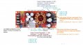
Please see updated diagram of the board These are what are known at the moment


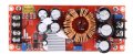
GS00936-12.jpg
 

Thread Starter

born2dive00

Joined Oct 24, 2016
285
Post 2 From the factory all is working as it should. all gear original
Tested and adjusted the over load to 10a
I tested the CV pot got a spread from 0- 87v
I could not load test the board as I don't have anything that uses that heavy of power
BUT when I turned the blue pot all the way down (off) it turned off the voltage out which was set at 84v and dropped down to 0, when I turned it on again the voltage started climbing up in increments in relation to the amps at the conversion rate. example
10mah max volt out was something like 20v, at 100mah something like 38v.
500mah like 75v and 1 amp the full on output of 87v.
These are roughly what I remember, I remember seeing the voltage step up as i increased the CC pot.


71yRgyEYl5L__SL1333_.jpg
 
Last edited:

Thread Starter

born2dive00

Joined Oct 24, 2016
285
Post 3 Original PCB pots removed servo connector pins soldered in. original pots plugged in everything working as it should no problems length of wires not showing any issues with the board. only a .01v difference between the original location on the board to the remote location.
Again i did the same pot test as in the first post on this sequence. I got the same results.

P_20170626_212132.jpg
 
Last edited:

Thread Starter

born2dive00

Joined Oct 24, 2016
285
Post 4
I removed the PCB Pots from the wire.
The very first time I installed the cheap dial pots they did not work.

Come to find out with the cheap pots the solder was wicking in and or burning the contacts. delaminating the carbon tract, that is why they did not originally work.

I replaced them with cosmos pots and are much stiffer and easily soldered
I removed the PCB pots and installed the 2 Cosmos pots replacing the CV 204 PCB pot with a 204 Cosmos pot. and replacing the CC 502 PCB pot with a 502 cosmos pot.
I wired them exactly as they came off terminal 1 on board to terminal 1 on pot ....

Sorry no photo at this moment

When done soldering the 2 cosmos pots the circuit board worked beautifully and had full range of adjustment on both pots for CC and for CV. No problems with remote mounting pot for pot.

Again did the same test as in post 1 of this series. got 0-87v spread on the cv and the cc shut down the power when turned off. and stepped up as i increased the CC pot.


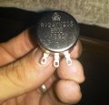
One of the cosmos pots
1P_20170626_212743.jpg
 
Last edited:

Thread Starter

born2dive00

Joined Oct 24, 2016
285
Post 5
Adding the fine tune pot.

Firstly I want to thank every one for their help here and a special thanks to Tony who has held my hand every step of the way. You guys have been a great help with this project. I know I am not the only one trying to add a fine tune pot to a DIY power supply there are many people out there asking how. So you fine gentlemen are doing a great service to me but also for the public who will come to read this. The more you explain the more I learn, I am not new to wiring on a macro level, but on a micro level and with pots (AHHHHH pots my arch nemesis)

I have been taking all your suggestions comments and pointers to heart and have been trying them so please don't think I am ignoring you. I am doing this series for the public as well to clarify my steps and actions for a few new members to this thread so we can find a solution together as a team. But I digress.

As I now had everything working correctly with just 2 pots (course pots) I wanted to add a fine tune pot to the system as the course pots were too Damn sensitive, caused by replacing a 10 turn PCB pot with a 270 degree turn Cosmos pot. I posted what I knew in a photo (nearly identical to post 1 in this series.

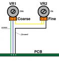
A member came up and said to use this illustration see illustration 1 below. I verified with the member that VR1 course was the larger pot (in this case the 200k) and the VR2 was the smaller one (in this case a 20k, I changed the 20k for a 2 k for ultra fine adjustment) I also confirmed that the left wire (green wire on VR1) was the positive power wire, and that the right wire (black wire one VR2) was the negative or ground wire.
I color coded the wires so I could keep track of what were what. I also added the corresponding numbers to the pins for perfect clarity as the order on the board are reversed from the illustration, i.e.321 instead of 123

ON THE CV SIDE, leaving the CC with just the one pot.
I proceeded to hook it up exactly the way the photo showed.
I then powered the unit up and tested the VR1 dial adjusted correctly left off/low, right high on, with a full spread 0-87a
I then turned the fine pot and discovered it was reversed left was high and right was low Not a big issue,
So I kept the yellow wire connected to terminal 2 and desoldered the terminal 1 and 3.
I then switched the yellow bridge from terminal 1 to terminal 3.
I then switched the ground wire from terminal 3 to terminal1

I retested and the CV Course dial worked 0-87v with the CV fine pot on zero. I brought the voltage down to exactly 45v and adjusted the voltage with the trim pot (left full off right full on) I turned the pot full right full on and the voltage climbed to 45.9v turned the voltage down and it stopped at 45v.so this gave me nearly 1v resolution.

I then proceeded to do the same setup including reversing the fine pot terminal 1 to terminal 3, moving the ground from terminal 3 to terminal 1 on the pot.

I proceeded to do the same test as in post 1 of this series (as I did not have a load I could test) I turned both of the CC pots off and the voltage dropped to 0, I just cracked the voltage on the CC course pot open and turned the fine pot up, I could see the voltage climbing and stopping at certain conversion points. (so I assume that the CC pot is working correctly)

So at this point everything seemed to be working fine, I had course and fine on the CV working (although I planned on changing the 2k for a 20k cause I did not need an ultra fine adjustment of .9v something like a range of 2 or 3 volts would be more feasible for my use but I digress) on the CV course
left was off/low right was on with a voltage spread of 0-87v. For the CV fine, left was off/ low was on with a voltage spread of .9v and the CC pots appeared to be doing the same. left off right on voltage drop when off and voltage stepping up in increments as I increased the pot on the fine.

I was planning on doing a load test that evening to verify the current load was working. Continued to next post


Coarse N Fine Pots (2).png
 
Last edited:

Thread Starter

born2dive00

Joined Oct 24, 2016
285
Post 6 the problems begin with the pots.
So as I said I was planning on doing a load test on the setup in post 5 and I got a message from a member saying that he made a mistake that the first illustration (in post 5 will not work) that I need to use the second illustration of a voltage divider Please see drawing below.

So in the evening I went home and rewired the pots according to the members second illustration of the voltage divider..
EXCEPT I wired it up NOT with a 20k pot but with a 2k pot.
I wired both the CC and the CV pots as shown in the schematic.
Before powering the unit I turned all the pots to the off position and slightly cracked them open less than1/16 of a turn. because this schematic looked familiar. I will come back to this later.

I powered the system with the CC 5k course and 500ohm fine and the CV with the 200k course and the fine 2k pots. The voltage reacted normal when I adjusted the CV course pot but not when I adjusted the 2k pot, there was no reaction.
I adjusted the CC course down to 0 and the unit shut off the voltage I just cracked the course pot open and tried adjusting the CC looking for a step up in the voltages at different conversions but nothing.


New Coarse N Fine Pots.png
 

Tonyr1084

Joined Sep 24, 2015
9,744
A dimmer will work only up to 4 feet and only for a short time and its limit is normally about 12-24v.
I have tired that before. as soon as you try to cut 6-8 feet of foam with 50-80v, it overloads and smokes out.
First of all, a short wire will have a lower resistance and therefore a higher current. The longer wire will distribute the heat evenly over the entire length of the wire. So your statement that a dimmer will work only up to 4 feet - I don't buy that for a second. Welding wire gets VERY hot when it's 1/8th of an inch to 1/4th of an inch. Hot enough to melt the metal it's coming in contact with. If you want a slightly cooler molten puddle you stick out a little further, up to a half inch, even more. So using a 9 foot wire did not make my welder work any harder. In fact, the welder handled the longer wire with greater ease than the shorter wire - which it's designed to handle. Sorry, I reject your premises that a short wire will work on a dimmer while a longer wire will burn it out.

if you bounce one end one direction say up and down at the same frequency, on the other end it will bounce at a different speed. this difference will will send the wave back to the starting point Where you are bouncing the cable. causing a disruption in the wave. I guess like a harmonic wave in a tuned pipe. As the imbalance tries to cancel out it creates a cold spot on the wire until it stablizes and starts resonating at the correct frequency.
Electrons travel at the speed of light. At that speed, in ONE NANNO SECOND light will travel slightly more than 11 inches. For the life of me I can not conceive of a wire being hot in harmonic places while remaining cold where the harmonics are opposing each other. I UNDERSTAND your illustration, but in electron flow, the current moving through the wire will be uniform throughout the entire length. Again, I reject your premises.

If you look at the industrial foam cutters used for 8' and up you will see that (most) are DC and use constant current with large capacitors to I guess stabilize the current.
Interesting note: Capacitors do not pass current. They charge and discharge. In a DC system they smooth VOLTAGE ripple but have no effect on current. Well, actually they do, but it's very little effect. More of a nuisance to engineers than a planned part of the design (my opinion)

Tony, do you know of any other way to turn on and off the short protection
Sorry, I have no experience with the board you're using.

Could you tell us what you meant when you said you used 90˚ servo pins? Educate me please - what is "servo wire"? And what are "Cosmos" pots please? I'm hoping these things are not like a 25µF diode you described in one of your earlier posts.
 

Thread Starter

born2dive00

Joined Oct 24, 2016
285
Post 7

Remembering that this member said that he did not know if the 2k pot would provide sufficient swing at lower voltages I pulled the 2k and replaced it with the 20k pot. double checking the schematic again to make sure it was right. I powered the unit up.

Well let me say this it was not fun. with the setup done as in photo, The voltage screamed way past the 87v on its way up to 114-120v I immedatly disconnected the power and the voltage dropped back down to 35v or there abouts. I again checked my the schematic and verified it with the wiring Please see photos 1,2 and 3.

1 I then turned Both of the CV pots (full left) off expecting to see a 0 voltage out reading, and proceeded to plug it in and again it screamed up to 114-120v I disconnected it,

2.still trying to get the voltage to turn off Next I tried to with both of the CV pots full on, (thinking I might have reversed the tuning) same thing
Trying to get the voltage to turn off, I then went and turned the CV course pot to full on (right) with the fine pot off plugged it in again it screemed up past the 87v (which the unit is rated for) up to 114-120. I disconnected it

3 still trying to get the voltage to turn off, I tried it again, with the CV course off (Full Left) and the Fine On (full right) again same problem.

4 Still tryingI turned the CV course on (full right) and the CV fine off (Full left) same problem

Next I turned both CV pots halfway to see if this would solve, expecting and hoping that the voltage would be 35-45v but nope Zoom back up to 114v

So then I turned my attention to the CC pots I turned both the CC pots to off position plugged it in and just cracked I mean a hairs width to turn on the power, zoooooomm up goes the power un regulated. disconnected it
Then I tried with the fine and course off, Nothing no movement on the voltage I then (thinking that the fine might be reversed) turned the dial full power on, and knowing that the CC course was working, I again cracked the power on zoom up goes the power and no adjustment on the fine.
I disconnected the power and stopped to think.

Next step on post 8
current wired system.jpg

fine set to low.jpg fine set to high.jpg
 
Last edited:

Thread Starter

born2dive00

Joined Oct 24, 2016
285
Tony Please see post 71, it shows a cosmos pot cosmos is the MFG
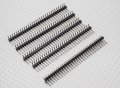
Please photo below, Servo pins in the rc world originally designed for the rc servos other wise known as Header pins in the electronic world
I never said those were my ideas, this is only what I have read and have been told, I am not an electronic engineer, I have no clue why you get hot and cold spots on the long wires but you do.
All I know is what I have been told, that to avoid those problems is to use DC... I don't know, I have used DC and never had problems. But I also use Nichrome wire vs most people use a simple guitar wire. so maybe that counts for something.
190mn.jpg

First of all, a short wire will have a lower resistance and therefore a higher current.
Could you tell us what you meant when you said you used 90˚ servo pins? Educate me please - what is "servo wire"? And what are "Cosmos" pots please? I'm hoping these things are not like a 25µF diode you described in one of your earlier posts.
 

Tonyr1084

Joined Sep 24, 2015
9,744
I powered the system with the CC 5k course and 500ohm fine and the CV with the 200k course and the fine 2k pots. The voltage reacted normal when I adjusted the CV course pot but not when I adjusted the 2k pot, there was no reaction.
I adjusted the CC course down to 0 and the unit shut off the voltage I just cracked the course pot open and tried adjusting the CC looking for a step up in the voltages at different conversions but nothing.
Of course nothing happened. If you start with a coarse setting of ZERO volts, the fine tune can only tune between ZERO and ZERO. You first have to set the coarse pot to some setting, starting with the fine tune at the half way setting. Then tune in the coarse voltage (or CC) you desire. Then tuning the fine tune pot will you see a reaction. The coarse pot sets the range PERCENTAGE WISE. The fine tune pot expands or contracts the range. You won't see any result with the coarse set to zero.

Imagine a foot ball field - 100 yards long. Lets call that your coarse setting. Now imagine that you can stretch or shrink that field. THAT is what the fine tune pot does. So if the ball is on the 50 yard line and you stretch the field by 10 yards, you may still be on the 50 yard line, but the goal is now 55 feet away. OR if you shrink the field, the ball is still on the 50 yard line and you shrink the field by 10 yards, now the goal line is only 45 yards away. Remember, the WHOLE field is being stretched or shrunk.

The original drawing wouldn't shrink or expand the field, it would just add weight to the football.

For some unknown reason; if you liked the way the original drawing worked then by all means, pursue it. If you have success - great. You've proven me wrong. And I'm HIGHLY confident that if anyone out there disagrees with my methods or conclusions they'd have spoken up. It's happened before and I expect it will happen again. I'm not above being wrong, admitting it, and learning from it. I readily accept correction when offered. So far I haven't seen anyone disagree with anything I've posted. But that doesn't say anything either. Just says nobody sees anything wrong or nobody cares to speak up if it SHOULD be wrong. If it is - HEY! I'm sorry. So from here on out I think I'm going to dismiss myself from this conversation.

Do as you wish. If you have 25µF diodes then maybe you have muffler bearings as well.
 

Tonyr1084

Joined Sep 24, 2015
9,744
Tony Please see post 71, it shows a cosmos pot cosmos is the MFG
Please photo below, Servo pins in the rc world originally designed for the rc servos other wise known as Header pins in the electronic world
And I'm supposed to know that a "Cosmos" pot looks so different from all other pots? Sorry, but header pins are header pins. Excuse my ignorance.

I AM setting up for one final post. Be back in maybe 20 minutes.
 

Tonyr1084

Joined Sep 24, 2015
9,744
Your "FINE" adjust ? ? ? If you turn it all the way to one side your system will see an additional 2K (or 20K). If you turn it all the way to the other side your system will see NO additional resistance. Hence, your fine tune will be in bypass mode, meaning it's adding nothing to the circuit. It's acting like it's just a jumper wire and nothing more. SEE BELOW. And you don't have to keep referring to me as "Another member". My name is Tony. I'm proud of my name and never ashamed to admit if I did or said something wrong.

POTS.png
 

Thread Starter

born2dive00

Joined Oct 24, 2016
285
Tony I have never insulted you, I have never said you were wrong and I have never criticized you. I am just as confounded by this as you are and as others here are. Just because setup 1 appeared to work does not mean it is correct! by your own statement you said " I am convinced that the second setup is correct" so if the setup is correct, then I am trying to figure out how to get to work correctly. You are not the only person that said that is how it "should be" I had a guy at the electronics store tell me the same thing as your second drawing, he even wired it up, taping the wires down so I could solder it correctly when I got home. I did just as he instructed as in your second diagram and Poof went my LCT3780. So some funky monkey is going on here. That is what I am trying to figure out with your and others help. I

I am writing this log for everyone involved and for the general public in order to help others who have same questions.

I believe that you might have misunderstood what I was attempting to do. With all the pots in the off position, there should have been no voltage out.
Even with the CC pot on, if the CV course and fine pots are off there should have been nothing going out. BUT there was voltage going out voltage of 114v. That is what I was testing when I turned the CV pots to zero to see if there was voltage going out when there should not have been and it was un controlled.
Only by turning the CC course pot off did it cut the power out.

Of course nothing happened. If you start with a coarse setting of ZERO volts, the fine tune can only tune between ZERO and ZERO. You first have to set the coarse pot to some setting, starting with the fine tune at the half way setting. Then tune in the coarse voltage (or CC) you desire. Then tuning the fine tune pot will you see a reaction. The coarse pot sets the range PERCENTAGE WISE. The fine tune pot expands or contracts the range. You won't see any result with the coarse set to zero.
 
Top