Unable to replace the pot of a DC motor speed control by a Hall sensor

Thread Starter

Altair2

Joined Aug 9, 2013
24
Hi, I have a PWM DC motor control from Aliexpress that has a 10K pot as the speed control. It works very well and is smooth.
I disconnected the pot and put in its place an e-bike hall-effect speed control. Wiring is correct, hall sensor works and its output goes where the center tap of the pot was. The controller doesn't recognize the voltage as a valid input apparently. The motor doesn't turn at all.
Is it possible that this controller, being based on a microcontroller (there is only an 8-pin chip as the active component besides the two Mosfets and a dual diode), does a check of the potentiometer on power-up, but not seeing what it expects, keeps the output off.
I've done this replacement before, on other speed controls, and it worked OK.
What do you guys think might be happening here?
My plan was to make an adapter to expand the 0.9-4.4V output of the Hall throttle to the 5.2-0V that the controller requires.
Yes, the voltage of the pot is inverted, 0V results in full speed.
Thanks|
 

Attachments

Last edited:

KeithWalker

Joined Jul 10, 2017
3,615
The circuit probably uses a capacitance - resistance charge or discharge time for input, like the original computer joystick interface.
 

Thread Starter

Altair2

Joined Aug 9, 2013
24
I just checked the voltages on the pot. It's all clean DC, my scope can't detect any HF on the lines. However, there is a 470uF Low ESR between + and - of the pot! Why would they need such a high quality cap if HF wasn't involved?
 

Alec_t

Joined Sep 17, 2013
15,149
Wiring is correct, hall sensor works and its output goes where the center tap of the pot was.
Where do the supply terminals of the Hall sensor go? I believe that in some motor controllers the pot is wired as a simple rheostat between V+ and the top of a resistor going to V-.
As Max says, some reverse engineering may be necessary.
 

Thread Starter

Altair2

Joined Aug 9, 2013
24
I connected the Hall to the same terminals that the pot uses. One is the ground of the whole circuit, common with the input supply and one of the motor terminals. The other has 5.2V that comes from the microcontroller.
Edit: The motor is not common with the ground. I could unsolder a bunch of parts to reverse-engineer the design, but I doubt I would be able to make it work with a Hall sensor.
 
Last edited:

Futurist

Joined Apr 8, 2025
940
Hi, I have a PWM DC motor control from Aliexpress that has a 10K pot as the speed control. It works very well and is smooth.
I disconnected the pot and put in its place an e-bike hall-effect speed control. Wiring is correct, hall sensor works and its output goes where the center tap of the pot was. The controller doesn't recognize the voltage as a valid input apparently. The motor doesn't turn at all.
Is it possible that this controller, being based on a microcontroller (there is only an 8-pin chip as the active component besides the two Mosfets and a dual diode), does a check of the potentiometer on power-up, but not seeing what it expects, keeps the output off.
I've done this replacement before, on other speed controls, and it worked OK.
What do you guys think might be happening here?
My plan was to make an adapter to expand the 0.9-4.4V output of the Hall throttle to the 5.2-0V that the controller requires.
Yes, the voltage of the pot is inverted, 0V results in full speed.
Thanks|
What is the part number of the Hall device?
 

Thread Starter

Altair2

Joined Aug 9, 2013
24
I don't know. It's inside a thumb throttle assembly for an e-bike or any other vehicle. It runs on 5volts and outputs 0.9 - 4.4V like all linear Hall devices.
 

Thread Starter

Altair2

Joined Aug 9, 2013
24
I'm trying to replace the potentiometer of a PWM speed control, by a thumb throttle that is based on a Hall sensor, as practically all thumb throttles do. It's easier to actuate than turning a pot.
 

panic mode

Joined Oct 10, 2011
5,189
Hi, I have a PWM DC motor control from Aliexpress that has a 10K pot as the speed control. It works very well and is smooth.

good that you never posted link to the item or any additional pictures from other angles. we all love to just waste our time guessing what people have there. seriously, try posting some data.

I disconnected the pot and put in its place an e-bike hall-effect speed control.
again, you cannot be serious... you think there is only one type of e-bike out there and that we all know what the used speed controls are? and assuming that sensor produces analog output, what makes you think that PWM controller you have is using trimpot as potentiometer and not as variable resistor?

Wiring is correct, hall sensor works and its output goes where the center tap of the pot was.
again. how do you know that is correct?

Is it possible that this controller, being based on a microcontroller (there is only an 8-pin chip as the active component besides the two Mosfets and a dual diode), does a check of the potentiometer on power-up, but not seeing what it expects, keeps the output off.
I've done this replacement before, on other speed controls, and it worked OK.
you keep making assumptions.... why do you think this is a microcontroller and not some analog RC oscillator? not all PWM controls are created equal. some do accept analog voltage as setpoint, others do not. besides, "done that on other controllers" tells us nothing since we do not know what THIS controller is, much less that those OTHER controllers were.

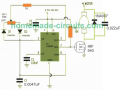
here is an example of PWM controller that does not accept voltage as input. and yes the only active component is an 8-pin IC which is not a microcontroller...
1785686997646.png

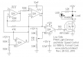
and here is an example of PWM controller that can use voltage as input.
half of IC produces triangular wave (also can be saw tooth or reverse sawtooth).
then the last opamp simply compares is the triangular wave is above some fixed voltage set by potentiometer. that potentiometer can be removed and you can bring DC voltage from some sensor. but keep in mind that in this example 12V supply means that control voltage need to be in range 2.6-9.3V.
1785687165996.png

btw, there is plenty of 8-pin ICs that are dual opamp. there is nothing in the way to use one opamp or comparator as a relaxation oscillator, and another as comparator, much like in above circuit. in fact here is what dual comparator (LM339 or similar) based PWM controller may looks like:
1785689952335.png

so PWM controller could still be completely analog and using 8-pin IC. to really confirm suitability of the mod you are attempting, it is necessary to identify IC or at least measure voltages and/or waveforms on all pins, and take a good look at the board from all sides - something you did not do and then by not sharing anything of value, you choose to leave us blind too.
 
Last edited:

panic mode

Joined Oct 10, 2011
5,189
My plan was to make an adapter to expand the 0.9-4.4V output of the Hall throttle to the 5.2-0V that the controller requires.

you can do that...

but while at it, why not the entire circuit so that no adapter is needed.
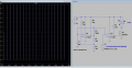
here is one idea based on those comparators. the R3 can be dropped in value or capacitors can be reduced to increase frequency to not audible range.
1785692670406.png
 
Last edited:

Alec_t

Joined Sep 17, 2013
15,149
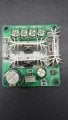
The three suggested circuits shown above each use a single FET, whereas the pic in post #1 shows the motor control with three power semiconductors on individual heatsinks.
Edit:
Presumably two paralleled for power sharing and one for the double diode for reverse-polarity protection.
This looks like the Aliexpress controller.
On the socket for receiving the control pot plug, the pin nearest the big 470uF cap is ground, next is the pot wiper, last is +5V. Are your Hall connections in accordance with that?
 
Last edited:

Thread Starter

Altair2

Joined Aug 9, 2013
24
good that you never posted link to the item or any additional pictures from other angles. we all love to just waste our time guessing what people have there. seriously, try posting some data.
I wasn't sure posting links was allowed here, as this is my first post since 2017.
So here you go:
https://www.aliexpress.com/item/100...|x_object_id:1005005732677192|_p_origin_prod:

And the thumb throttle is this:
https://www.aliexpress.com/item/100...|x_object_id:1005010470976718|_p_origin_prod:

again, you cannot be serious... you think there is only one type of e-bike out there and that we all know what the used speed controls are? and assuming that sensor produces analog output, what makes you think that PWM controller you have is using trimpot as potentiometer and not as variable resistor?
I'm not assuming the throttle produces an analog output, I tested it!
I never mentionned any trimpot.
Altair2 said:
Wiring is correct, hall sensor works and its output goes where the center tap of the pot was.
again. how do you know that is correct?
Because one side of the pot has a constant 5.2V, the other side is connected directly to ground, and the wiper with a variable DC voltage goes to the chip. It wasn't difficult to conclude that it was wired as a variable voltage source. That's why I connected my variable voltage source (the Hall throttle) to the place where the pot was previously connected. And how did I know that my connections were correct? Because I tested the throttle in-circuit and it was outputting its variable voltage to the correct pin of the circuit.

Yes I assumed the chip was a microcontroller because there isn't any waveform or AC on the wiper of the pot. The designs you show will have activity on that line.

I didn't ask for a design, I wrote: What do you guys think might be happening here?
I just wanted ideas on why this board can't work with an applied external DC voltage, when the pot is actually doing the same job.
 

panic mode

Joined Oct 10, 2011
5,189
i still see no values on any of the parts, so all i can offer is speculations.
if there is no activity at node where potentiometer or sensor connect to but one worked and other does not, i can think of some scenarios...
one is that there is impedance mismatch. in other words you may have to buffer the signal. because one thing is to measure voltage using DMM which has high input resistance, the other is to do the same with some load.
the other is that in process of replacing the potentiometer by throttle sensor you damaged something. many products are susceptible to ESD. one test you can do is put potentiometer back to see if the board still works.
 

Alec_t

Joined Sep 17, 2013
15,149
Just a thought. According to the pics of the similar controllers in your link and the link I posted (post #16), the pot connections might be reversed (judging by the red and black wires). While that's not significant for a simple pot, it would be for a Hall device.
 

Thread Starter

Altair2

Joined Aug 9, 2013
24
You're right Alec_t,
I had noticed this when I got the board. I checked the voltages on the pot and everything was in the correct place for a pot wired as a voltage divider. It's just that they interchanged the yellow wire with the black one. Typical chinese lack of QC. I correctly wired the throttle, it works perfectly out of circuit, and also in-circuit. Its output goes where the wiper of the pot was going and the voltage varies as it should. The only difference is that the chip doesn't respond to that. If I plug the pot back in, the board works fine.
About your previous post, the first pin near the big cap is the +, then wiper and last GND. The pot sends 0V at max and 5.2V at min.
On the power devices, the one that faces the pot connector is a STPS20S100CT twin diode. I don't think there are 2 parallel output devices, they need a way to generate the 5.2V supply off the 90V (max) input, so they must have a linear regulator in there, as there aren't any inductors on that board for a switching power supply. I would have to unsolder the other 2 power devices to see what they are.
Thanks for your comments!
 
Top