Why when I Replace the PCB pot with manual pots, the manual pots wont work when correctly wired

Thread Starter

born2dive00

Joined Oct 24, 2016
285
Sorry Tony, you referred to me as OP Other Person, when speaking with another person, I thought I was being politically neutral and correct by not including names..
As for the pot issue, I understand what you have drawn and have explained But it is not working.

1. if the main course pot is in the left positon OFF/low, and the fine is in what ever position, there should be no voltage coming out.
2. If the main pot is main pot is in say 1/4 on, then by turning the trim pot to the right in your post should increase the voltage out as the resistance gets less. (it is not happening) it is the same voltage on the output if the course pot is full on in the middle or full off, same for the fine pot if the main pot is 1/2 way, then depending on which way you turn the trim pot it will increase slowly or decrease slowly or stay constant
It is not. It is sending voltage out excess of 114v regardless of where the trim or course pots are at.
i.e. with the 200k and 20k
course left fine left full power
course left fine right full power
course right fine left full power
course right fine right full power
course center fine center full powe

SO by your diagram Which I understand fully, at 50 percent of the pot you should get roughly 50 power out Aproximately as they are linear or about 35-45v ball park. AND it should stop and stablize at 45v BUT when I place all pots at 50% Excess full power 40v more than full power.
With the 200k and 2k nothing on the fine only works on course.

TONY Here is some information that I just found out,
there is continuity between pins 2 and 3 on the CC and CV pins on the board,
Pin 2 sounds off the continuity alarm when grounded to the DC- Out on both the CC and the CV.
Pin 3 also sounds the continuity alarm when grounded to the DC- Out on the board.

SO does that mean that BOTH pins 2 AND 3 are grounds on the CC and the CV?
if yes how does this affect the second diagram?

[QUOTE" Another member". My name is Tony. I'm proud of my name and never ashamed to admit if I did or said something wrong.[/QUOTE]
 
Last edited:
Thread Starter

born2dive00

Joined Oct 24, 2016
285
Post 8
So remembering what Keep it simple and several others said about long wires, I cut another servo plug off to 2" leads and tested the circuit the system again as in post 7... (sorry no photos, as it was past 1am and I had to get up at 6am to teach)

Short wires made no difference what so ever I had the exact same problems as before, CV pots did not work, CC fine pot did not work, only the CC course worked and it was ultra sensitive.

So with only the CC Course pot working and having no reaction on any of the CV pots and the CC fine pot not working, I wanted to check that the board was still ok, so I disconnected the 500 ohm pot and wired the 5k back to the original position as in post 3.

I powered up I the CC course the 5k worked, but to my supprise the voltage never exceeded the recommended voltage of 87v, and I had gain on the course 200k pot which turned up and down the power accordingly. BUT the 20k fine pot still did not work.

See the photos below

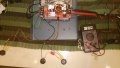
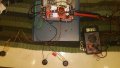
CC fine pot 500 ohm pot disconnected, 200k Large Dial and 20k Small Dial CV pot connected no gain on CV fine. CC 5k pot left pot Wired directly in.

fine set to high.jpg

CV Fine pot turned slowly to high side (no voltage change) 5k CC pot directly wired in . cracked open 1/2 way.
fine set to low.jpg
 

Thread Starter

born2dive00

Joined Oct 24, 2016
285
So in recap the
order of the back pins side to the top of photo are left to right 321 Black blue green
This had a 200k PCB on board that was removed and "header pins" (thank you tony) soldered to them to run servo wire.
Pin 1 is the power pin (114)v
With unit powered off, pins 2 and 3 have continuity to ground (DC - OUT) as well as having continuity directly across them.

The front pins are left to right 123, yellow orange brown
this had a 5k PCB pot on board that was removed and header pins soldered to them, to run servo wire
Pin 1 has 4 v when powered,
with unit powered off, pin 2 and 3 have continuity to ground (DC- OUT) as well as having continuity across them.

I do not know it this means that both pins 2 and 3 are directly grounded or if there is another reason.
If both pins are grounded then would that not explain why Tonys diagram 1 worked and diagram 2 would not work?

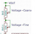
Someone mentioned that it sounded like they are using the pots as rhiostats. is there a different way to wire this up then that we have not discussed?? parallel?

all pots work but may not be correct for board
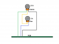
Coarse N Fine Pots (2).png
Illustration 2 with 2k no fine adjustment, with20k no fine adjustment nor voltage control
New Coarse N Fine Pots.png
Unknown pots used as rhiostats?
Untitled.png

If any one is willing to take a shot at this I am willing to try about anything. To get this to work PROPERLY with just 2 pots for the CC and 2 pots for the CV.
 

Thread Starter

born2dive00

Joined Oct 24, 2016
285
@ RF@@ I need to see exactly how the wires are hooked up in an illustration R!F I have fubared 2 of these converters already (perhaps) because I misunderstood the POT schematic or the schematic was not fully illustrated. i.e. pin 123 on the board and pin 123 on the pot. without the numbers is pin 123 as you look down on it left to right, or is it pin 123 left to right as you look down on it from the back, yhou will see illustrations both ways.

With tony illustration it clearly shows what is what, AND if I had a question he gave me a very very clear answer. He is a very logical thinker.
R!F I have taken your points but some points were un clear, it was like I gave you the start now figure out the rest. Which is very fine for some who have delt with complex circuits or took electronics classes in school. They did not have that when I was growing up.

So if I have offended you, or if you feel upset, I apologize I just don't want to throw another $50 in the garbage by connecting something in a way it looks right. I need definitive answers before I do more. I do very much value your opinion R!F you were a great help with the shielding of the RC system

@Tonyr1084
My suggestion includes your idea but OP is not following my suggestion to figure out his problem. :confused:
 
Last edited:

Thread Starter

born2dive00

Joined Oct 24, 2016
285
Tony it is not that I like the original drawing and how it worked, It is the ONLY drawing that worked thus far. Like I said before It worked but that does not mean it is correct!

Tony I hold your experience and skills in high regard, you have helped me out a lot more than others. I have never criticized you in any way, on to contrary, I ask you as a valued person to stay till we along with others get this figured out.

As far as the muffler bearings no, I don't have any at the moment, that must be akin to the blinker fluid you have been adding in your pickup truck, ;-) LOL

For some unknown reason; if you liked the way the original drawing worked then by all means, pursue it.
So from here on out I think I'm going to dismiss myself from this conversation.
Do as you wish. If you have 25µF diodes then maybe you have muffler bearings as well.
 

Thread Starter

born2dive00

Joined Oct 24, 2016
285
Bertus,
I have them working without the fine tune pots please see newest posts 68- 73, 82,83
This is everything that I know at this moment.

Take a look at the newest posts R!F I did try it with the short leads
Pots are working with long and short leads when the I am using only course (a match to the value pot that was on the board.)
I when connecting the trim pots long or short with 2" wires, with diagram 2 no difference still the same problem.

If OP is replacing the POT's with long leads that the problem lies in noise pickup. OP can use shielded wires and try.Since they are SMPS, the switching frequency could be causing havoc in the long wires
Hello,

I would first try to get it working without the fine tune pot.
If that works, you could post the results and then we cal look how to implement the fine tune pot.

Bertus
Make the connections to your new pots as short as possible and report back.
 
Last edited:

Thread Starter

born2dive00

Joined Oct 24, 2016
285
I did find out something interesting though
The CV 2 and 3 are not grounded to the - they are commoned to the DC+ output

Please see drawing below
if you have any questions please let me know or trouble shooting tips let me know

I made a small mistake pin 1 on the CV has 5-7v less than the other pins when turned up full way with 1 pot.
when turned down it is 0 while the others eventually read 0 I believe this delay is due to the capacitors on the DC output side.
GS00936-7.jpg
 

Alec_t

Joined Sep 17, 2013
15,149
I don't see how pins 2 and 3 can be common, since you measure 86Ω between them!
When measuring voltages, use the DC- output as the reference point (black probe connection) and quote all voltages with respect to that. Then we'll all be singing from the same hymn sheet.
 

shortbus

Joined Sep 30, 2009
10,049
Short bus, On small foam cutting projects, the Ac systems work fine. up to 4' at 6 ' it starts to get jagged cuts and at 7' or more it looks like someone cut the foam with a chain saw. Because the heating and cooling of the systems and getting hot spots on the wire. This happens when you use AC power over a long wire (I don't understand it but it has been related bouncing a long cable secured on both ends. if you bounce one end one direction say up and down at the same frequency, on the other end it will bounce at a different speed. this difference will will send the wave back to the starting point Where you are bouncing the cable. causing a disruption in the wave. I guess like a harmonic wave in a tuned pipe. As the imbalance tries to cancel out it creates a cold spot on the wire until it stablizes and starts resonating at the correct frequency. The ac in the cutting wire, as long as the wire is short or is stablized, will work fine, as soon as it starts getting long, (as I understand it )this bouncing back and fourth is what causes the hot and cold cycling, and destroys the rhiostats,
I say this is total BS. If the wire is cutting a 'chainsaw' finish it is probably due to to low of a speed in cutting. Allowing the melted plastic to not get left behind in the cut. Or not using a high enough current on the wire. If you setting the wire when exposed and then hoping it will keep the same temperature as it is cutting, you're wrong. Wire temp needs to be adjusted to when it's cutting not in open air, the material being cut will drop the temp. Just like heating an empty pan to a certain temp and then adding water to the pan, it drops the temperature until it reheats. AC or DC watts are still watts.

If you look at the industrial foam cutters used for 8' and up you will see that (most) are DC and use constant current with large capacitors to I guess stabilize the current. anyway they cut like champs but they are between $2,000 and $60,000 which is way more than what I have to spend
Maybe, don't know. But if they are using DC, I guarantee you they aren't doing it with a switching power supply. They're doing it with a LINEAR power supply. Basically a transformer a bridge rectifier and an output capacitor.

You keep mentioning your output voltage, don't worry about that. It's the current that does the work in a heater. The same as a light bulb, all household bulbs are the same voltage. It's the wattage that changes, and makes some brighter and hotter than others. Watts are volts times amps(current). Trying to keep a certain voltage and a certain current out of your power supply, you're just chasing your tail, not going to happen, especially not with the wimpy switcher you are trying to use. Sorry but facts are facts.
 

R!f@@

Joined Apr 2, 2009
10,007
@born2dive00 It's OK buddy. I am not offended. I just want to get the facts straight. :)

You are trying hard, I can see that. Persistence is good, for a good cause. :D

Like to know something.
When you desoldered the original trim pots, did you use a good soldering techniques ?
Just wanna know that you did not pull out a vias ? :oops:
That is double layer PCB. Poor desoldering will lead to broken vias ?
Can you confirm that there is no damage ?

by the way, fine tune pots have basically 1V range. Increasing the fine pot value might be an issue.
 

Thread Starter

born2dive00

Joined Oct 24, 2016
285
Alec
86 on the pot value with the pots off. NOT 86 on the board with the pots removed.
With the pots removed there is continuity between pins 2 and 3, and depending if it is the CV or CC pot continuity to DC+ or DC- terminal

I don't see how pins 2 and 3 can be common, since you measure 86Ω between them!
When measuring voltages, use the DC- output as the reference point (black probe connection) and quote all voltages with respect to that. Then we'll all be singing from the same hymn sheet.
 

Thread Starter

born2dive00

Joined Oct 24, 2016
285
Well soldering is clean and clear on what I did. With this I have had A LOT of experience over the years, Just finished building a basestation for FPV from scratch. (the chips were already made) but the rest I did works great too.

I doubled checked for broken connections the moment I get any chip or board from china. There is nothing wrong with it visually that I can see with the naked eye. nothing that appears broken or loose. there was 1 crappy solder job on a mosfet leg but I cleaned that up.

Yes it is a double layered PCB board but all the traces look well designed, and covered with the insulation. I smelled the board to see if I could get a whiff of burned epoxy resin from the actual board there was none which indicates that during the soldering process the board was not over heated when placing on the components and no signs of trace blistering.
I also smelled the components looking for a burnt electronics smell nothing. it all looks good.

Like I say the board is working with just 1 pot for the CC and 1 pot for the CV. it works well. but as soon as I add that freeking second pot....

As for the 1 v range, it depends on the pot value (as I understand). I have seen another guy (granted slightly different setup he was using a transformer) but his fine was 3v spread. with a trim pot 10 of the value of the course, and a .6v spread with a 1/100 value pot

@born2dive00 It's OK buddy. I am not offended. I just want to get the facts straight. :)

You are trying hard, I can see that. Persistence is good, for a good cause. :D

Like to know something.
When you desoldered the original trim pots, did you use a good soldering techniques ?
Just wanna know that you did not pull out a vias ? :oops:
That is double layer PCB. Poor desoldering will lead to broken vias ?
Can you confirm that there is no damage ?

by the way, fine tune pots have basically 1V range. Increasing the fine pot value might be an issue.
 

Thread Starter

born2dive00

Joined Oct 24, 2016
285
Ok short bus, how would you explain it then.
On a commercial DC unit with a 30g nichrome wire, on an 96" spread requires 70v at 1.3A which gives you a 600 degree wire (oh by the way they use constant current so when it does dip it automatically boost the power). They cut any thickness of foam at a rate of 1" per second. that means if you are cutting a 96" span across at 48" you can cut this if 48 seconds

Now others out there have used guitar strings, welding wire, wrapping wire, with welders, transformers rhiostats... as Tony said he gets a cut at 1-2 inches across 96" in 5-6 seconds. So to cut a sheet of foam lengthwise96" across the face 48" would take about 144 seconds or nearly 2.5 minutes

When you compare the cuts of example a and example b, example b it is jagged, choppy and wavy, yes it is relativly smooth but generally Exampler B requires sanding where as example a setup rarely needs any sanding. This is why why I said it cuts like a chainsaw.

But you don't have to take my word, I really don't care either way, I know what works and what I like, you know what works for you and what you like. So it really comes down to preference, availability and money. I don't have availability on some items needed, and I sure don't have the extra money to waste on buying one, when I can build one for 1/10 the cost.

I say this is total BS. If the wire is cutting a 'chainsaw' finish it is probably due to to low of a speed in cutting. Allowing the melted plastic to not get left behind in the cut. Or not using a high enough current on the wire. If you setting the wire when exposed and then hoping it will keep the same temperature as it is cutting, you're wrong. Wire temp needs to be adjusted to when it's cutting not in open air, the material being cut will drop the temp. Just like heating an empty pan to a certain temp and then adding water to the pan, it drops the temperature until it reheats. AC or DC watts are still watts.


Maybe, don't know. But if they are using DC, I guarantee you they aren't doing it with a switching power supply. They're doing it with a LINEAR power supply. Basically a transformer a bridge rectifier and an output capacitor.

You keep mentioning your output voltage, don't worry about that. It's the current that does the work in a heater. The same as a light bulb, all household bulbs are the same voltage. It's the wattage that changes, and makes some brighter and hotter than others. Watts are volts times amps(current). Trying to keep a certain voltage and a certain current out of your power supply, you're just chasing your tail, not going to happen, especially not with the wimpy switcher you are trying to use. Sorry but facts are facts.
 
Last edited:

Tonyr1084

Joined Sep 24, 2015
9,744
OP wants it to work with all the pots.
The Thread Starter (TS) can adjust the fine tune pot all the way down to zero volts and it will appear as if there is no fine tune pot. I understand the TS wants to build a complete unit the first go around. Sometimes that works, sometimes it doesn't. There have been many times when I've built something in its complete form only to discover something was wrong. Then I had to de-build and take it one step at a time until I uncovered my error(s).

Can I point out that we still don't know how this unit is working. We don't know if a Constant Current supply will vary the voltage based off of the resistance it sees or not. If so, and there's no resistance then there's no current. The voltage MUST fly to max in order to TRY to push a set current.

For the TS benefit: If you want a constant current of 5 amps and you have a very high resistance, lets pick 200Ω just for sake of argument; the supply will feed (if possible) 1,000 volts. That's how a constant current supply works. (that I know of) If you wanted 5 amps and you have a cutting wire of a mere 10Ω then the supply will push 50 volts through the line. If you have NO resistance (same as an infinite resistance) then the supply will (in theory) supply an infinite amount of voltage (times 5).

When testing for CC you MUST have a load on the system. And I'd advise doing the math before you put a load on. If you put a small motor on there, one that normally runs on 12 volts DC and you want to push 5 amps (again, just for example), that motor must have a reactance (resistance) of 2.4Ω. I can see that being the case, but if you were to put a tiny 5 volt motor (something out of an old tape recorder) it might have somewhere on the order of 0.01Ω. In that case the supply trying for 5 amps will deliver 0.05 volts.

I still say that we need a better understanding of how your unit works before we can qualifiedly answer what's going on with your circuitry. And I still stand by my second drawing. Having the fine tune pot in the middle of the coarse adjust won't (or shouldn't) do anything. That's why I redrew the picture showing the fine tune in series with the input to the coarse pot. You drew it correctly in post 75, so by all standard accounts and understanding it SHOULD work. Why it's not - unless we can know more about your particular board and how it was designed, all we can do is - um - well - guess.

By now I think you should understand what you're doing. One word of caution, soldering and re-soldering on a board over and over again leads to stress fractures in the via (plated through hole). A plated through hole is one that connects one side of the board to the other. And if you're working with a multi layer board, having as many as two, four, six, eight or more layers internally in addition to the two layers you can see on the board. I've seen boards with all kinds of goings on internally that if something goes wrong there's no fixing it. I worked as a micro section technician for four years and was certified to IPC 6011, 6012 and 6013, all having to do with construction of bare PC Boards (PCB's). I've seen first hand what over soldering does to a board. Measling and crazing of the glass fibers and the resin, which can crack inner traces and interconnects in the via's.

Telling you this just because if you're unaware, circuit boards can not be soldered on an infinite number of times. In the shop, if a board had to be reworked three times it became scrap - even if it was still working. It was not dependable. These were products that went to the bottom of an oil well while the well was being drilled. A failure meant high costs. Off shore oil rigs run at a cost of about $2,000 an hour just on the drilling time alone. And if something fails and they have to pull a 3 mile string of drill pipe out of the well - one pipe at a time - they'd get pretty pizzed if it failed. So reliability and dependability dictated that we couldn't (or shouldn't) use a board that had a particular solder joint reworked too many times. Three times was the cut-off. If it was still bad then the whole board went in the scrap bin. Which is where I got a lot of stock for a long time. But that was back in the 80's. So be careful about how much heat and how many times you heat up a solder joint. You COULD be causing your own failures, and you might not even realize it.
 

Tonyr1084

Joined Sep 24, 2015
9,744
as Tony said he gets a cut at 1-2 inches across 96" in 5-6 seconds. So to cut a sheet of foam lengthwise96" across the face 48" would take about 144 seconds or nearly 2.5 minutes.
Yeah, I'd agree with that. The cutting I did was on sheets two inches thick, four foot by eight foot. I always cut through the two inch dimension. In such a short cut I didn't see any waves. I cut my foam to fit into a basement room to act as sound proofing so that when I played music it wasn't bothersome to the people up stairs. (by the way, it's not a very good sound insulator)

I can't imagine where you're getting blocks of styrofoam (styrofoam is what I cut, but I suppose you could cut foam rubber and the likes too) 96 inches long by 48 inches thick. I'm sure it's out there. But if you're cutting this stuff then it's got to be for some sort of mass production. In which case I'd opt for the bigger bucks to get a machine designed specifically to do what you're wanting. But I still wonder why you need to control the current so precisely. A hot wire is all you need. TOO hot and you can run into problems. Too cold and you're going to get an ugly cut (as you said). But I have to imagine (and by imagine I mean I have no practical experience with this) whether the wire is 550˚ F or 650˚ F, you should still get a pretty good cut. If time is such a factor then again, I'd opt for the bigger bucks machinery. It's your project, build it as you see fit. If after you've finished your cutting and you want to repurpose this device - I can understand wanting to have the fine adjustment working.

Somewhere in the circuit there must be a "Sense" circuit. For a fine control you could isolate that part of the circuit and set up a fine adjust pot across the reference voltage feeding an op-amp (or comparator). But now you're working at circuit level where you need to know the reference voltage and how it's achieved. Not too long ago I modified a power supply from an old satellite power supply. It put out 12.05 volts but I wanted 13.6 volts. It wasn't a difficult build and I got a lot of help with it right here. Many of the people answering your questions are the same who answered mine. My repurposed circuit is out in the garage running as expected.

Whatever you come up with, good luck. I hope it gets working for you. But I wouldn't discount the notion you may have hurt the circuitry already with all the heat and testing you've (probably) done.
 

JUNELER

Joined Jul 13, 2015
183
Hi,
May i know what is your trying to prove by doing such idea.
Second see in schematic drawing (if you have it) where this pot is going inside the circuit.
You may changing the required resistance as it in original this will cause not to work the oscillator circuit.
 
Top