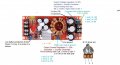
Now that I got the pots new pots working with help from all you kind souls,, using the photo below how do I wire in a fine tune pot??? a 500 ohm for the 5 k and a 2k for the 200k???
I would assume that if pin 3 is ground then pin 2 would likely also ring to ground using a continuity test meter. Current would be different but the potential to ground will likely appear to ring to ground. IF pin 1 is connected to B+ (common term for positive voltage on a voltage bus) then pin 2 is probably ringing to B+ as well when using the continuity meter.
For a true test one would test for voltages with the unit powered. The potential between pins 1 & 3 would read out as a voltage somewhere between B+ and ground.
Using the tone on the setting for continuity, if you touch the wiper pin out on the board and the ground on the vdc out put side it rings,
same as if you touch number 3 pin on the board to the vdc output side it also rings.
So I guess both the wiper 2 and pin 3 are both connected to ground????
Absolutly correct Tony, that is exactly what I did, unpowered I used the continuity tester 3 chimed/rang to ground as did 2 un powered.
I knew powered the unit up and got 114-120v on pin 1 and then tested ground on pin 2 and 3, only 3 then rang to ground, so that means powered up 2 must be a signal??
I would assume that if pin 3 is ground then pin 2 would likely also ring to ground using a continuity test meter. Current would be different but the potential to ground will likely appear to ring to ground. IF pin 1 is connected to B+ (common term for positive voltage on a voltage bus) then pin 2 is probably ringing to B+ as well when using the continuity meter.
For a true tenst one would test for voltages with the unit powered. The potential between pins 1 & 3 would read out as a voltage somewhere between B+ and ground.
I just hooked up my LTC 3780 and fried it when I tried to install a fine pot ( I think I wired something wrong, MY Mistake...).
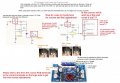
Below I have attached a photo of the schematic, the pin out, and how someone told me to wire the V adjust.
I have also wrote some questions on the photo I could use answers to.
Could one of you perhaps Tonyr with his wonderful artistic drawings, (THIS REALLY HELPED TONY) to visualize what I need to do with the LTC3780 to connect fine and corse? Please feel free to draw the lines on the file. And thank you all for your help!
Your assumption is correct about using the 200K as the coarse adjustment and the 2K as the fine adjustment. 10 turn or single turn - doesn't matter.
You make the assumption that both pins 1 & 3 are connected to ground - that is false. There is a potential voltage between pins 1 & 3, one of those pins are connected to ground while the other side is connected to VDC. The pot forms a divider network through a variable resistor. As you move the wiper you select a reference voltage for the rest of the circuit to work off of. So when you adjust (coarse) to your target voltage you get very nearly the voltage you want. You only use the fine adjust to tweak the voltage (the setting) for the circuit to work off of. So when setting the coarse setting put the fine adjust as close to center position as you can, that way you can adjust slightly up or down and zero in on the voltage you want.
As for worrying about being over the ohms limit - you don't have to. Using the total resistance won't harm anything. Remember, a pot is just a divider network with an adjustable pickup (the wiper) anywhere in-between the desired setting. You don't have to worry about being over the resistance. And pots are typically ±10%, so 202KΩ - - - I wouldn't worry.
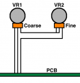
Actually, after giving it some more thought my original drawing won't achieve the fine adjust, all it will do is slightly alter the current in the circuit. The drawing below will do better at giving you a voltage adjustment (not current); which by the way, having the extra resistance wouldn't have given you any more current, it would have reduced the current. So my modification wouldn't have blown up the board. However, if you hooked the fine adjust across the Vcc & Vgg then that could be the reason why you blew out a board. Another good reason for the changes I made to my drawing. Minor changes but no matter what, you shouldn't have blown up a board from my first drawing. You should also understand that when setting to the lower limits the fine adjustment will become less affective whereas at the higher limits the fine adjustment should be more sensitive. Just be sure you never drop the resistance to zero across pins 1 & 3 on the board.
[edit] The new drawing should make it clear how to hook up the fine adjust pot (VR2). This can be on either side, connected to pin 1 (of VR1) or on pin 3 (of VR1). VR1 should be your coarse adjustment and should be wired in place of the original variable resistor that was originally on the board. VR1 should be the 200K and VR2 should be the 2K. If (in my original drawing) you got those reversed then that could account for blowing out the board. Be SURE to follow the drawing, and make sure everything is right before you power it up. If it blows up again - then there's something going on that I'm unaware of.
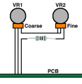
Tony would putting a resistor on the 3 pin on VR2 prevent this from over loading the circuit. I.e. Vr1 500k, Vr2 5k then on pin 3 of VR2 add a 500 ohm resistor between the pin on 3 and the board?
wouldn't the resistor prevent the pots from reaching 0 resistance potentially burning the system? basically acting as a safety???
Did I put the resistor in the correct spot? to achieve this???
On VR1 between pins 1 & 3 will ALWAYS be (in this case) 200KΩ. And I believe if you may have inadvertently mixed up the two pots when your board blew out, 200KΩ will never be anything different than the 200K across pins 1 & 3. IF you inadvertently put VR2 where I show VR1 then between pins 1 & 3 could have been as low as (in this case) 2K, which may account for the blown board. If you add the resistor as per your drawing it will just increase the resistance either slightly or significantly, depending on what you put there, but it will never cause any harm.
Personally I don't think it's needed. Even if VR2 is cranked all the way down to zero ohms, there will still be 200K present. So, no, you don't need the extra resistance.
One final thought on VR1 & 2, they need to be "Linear Taper" and NOT "Audio Taper" pots. You won't like the result using Audio Taper; their resistance won't sweep steady across the range of resistance on pin 2.
Hey Tony, the pots are linear of that I make sure of, I think I did just that, mixed up the 2k with the 200k in the wiring, many people say it wont matter, but I believe that it did in my case.
Here is why I was thinking of adding a resistor to leg 3, as it sits now with the new pots, fully cranked I am getting 88 volts on the output side of the unit. this is 5vdc more than the rated 83v. so by putting a say 200 ohm or larger I should in theory be able to drop this down to the necessary 83-85 vdc.
On VR1 between pins 1 & 3 will ALWAYS be (in this case) 200KΩ. And I believe if you may have inadvertently mixed up the two pots when your board blew out, 200KΩ will never be anything different than the 200K across pins 1 & 3. IF you inadvertently put VR2 where I show VR1 then between pins 1 & 3 could have been as low as (in this case) 2K, which may account for the blown board. If you add the resistor as per your drawing it will just increase the resistance either slightly or significantly, depending on what you put there, but it will never cause any harm.
Personally I don't think it's needed. Even if VR2 is cranked all the way down to zero ohms, there will still be 200K present. So, no, you don't need the extra resistance.
One final thought on VR1 & 2, they need to be "Linear Taper" and NOT "Audio Taper" pots. You won't like the result using Audio Taper; their resistance won't sweep steady across the range of resistance on pin 2.
Tony just for picture perfect clarity;
1. a. Do not use the first drawing that you made on any of the boards???,
b. Instead use the second drawing on post 34 correct??? Do I use the second design on all the pots on all the boards?? or is it specific to one or the other (ignoring values at this moment)
2. Bring the voltage and/or CC down to within the recommenced range by placing a resistor of appropriate size between pin 3 on the VR2 (fine pot) and pin 3 on the board. (this will act as a buffer preventing the board from exceeding recommended specs)
3 . VR1 is always going to be the largest pot that controls the course and has the highest value, and VR2 is always going to be the fine pot with lower value than VR1. Correct??
4. Pots should be linear taper Type B and never audio pots Type A correct.
5. Above all, follow the schematic in post 34.
Actually, after giving it some more thought my original drawing won't achieve the fine adjust, all it will do is slightly alter the current in the circuit. The drawing below will do better at giving you a voltage adjustment (not current); which by the way, having the extra resistance wouldn't have given you any more current, it would have reduced the current. So my modification wouldn't have blown up the board. However, if you hooked the fine adjust across the Vcc & Vgg then that could be the reason why you blew out a board. Another good reason for the changes I made to my drawing. Minor changes but no matter what, you shouldn't have blown up a board from my first drawing. You should also understand that when setting to the lower limits the fine adjustment will become less affective whereas at the higher limits the fine adjustment should be more sensitive. Just be sure you never drop the resistance to zero across pins 1 & 3 on the board.
[edit] The new drawing should make it clear how to hook up the fine adjust pot (VR2). This can be on either side, connected to pin 1 (of VR1) or on pin 3 (of VR1). VR1 should be your coarse adjustment and should be wired in place of the original variable resistor that was originally on the board. VR1 should be the 200K and VR2 should be the 2K. If (in my original drawing) you got those reversed then that could account for blowing out the board. Be SURE to follow the drawing, and make sure everything is right before you power it up. If it blows up again - then there's something going on that I'm unaware of.
1a) Correct.
1b) Correct. This is for all pots replaced. As long as you keep the proper value.
2) You don't need an additional resistor. Just use the fine adjust to tweak the voltage.
3) Yes, VR1 will always be the bigger pot.
4) Yes.
5) That's what I recommend.
The reason why you probably blew the board was because originally, between legs 1 & 3 the board expected to see 200KΩ, meaning if it were adjusted to 10 volts (for example) the pot would see 50 micro-amps. Using a 2KΩ in the wrong position would have resulted in seeing (at 10 V example) your board would see 5 milliamps. 100 times more amperage with the wrong pot in place.
Of course I don't know what the potential between pins 1 & 3 are in any of the circuits so all I can do is pick at random some example to make my point clear. (hopefully)
Tony, First I would like to thank you for all your hand holding, help and clear drawings, ( schematics I can understand 1/2 of the time but not when pots are concerned, I must see how the wires are connected) As you can probally tell Pots have always been and will continue to be my arch nemesis, I understand the principals of how they work if using 1, but more than that like what you have just done, forget it!!!
Again thank you very much. I owe you a drink of your choice once I am back in the states (I teach over seas) and in your neighbourhood.
I was going to post a video on you tube when this project is done, can I use your drawing to show how to hook up the course and fine pots, I know that there have been a lot of people out there trying to add these to the DYI Bench power supply. I am taking it one step further, as most people use only the 120w Ltc 3780 converter, I am using that as well as the 1500w converter to go from 0 up to 85v 0 amps upto 20 amps.
I am using my this power supply for hot wire cutting foam sheets up to 8' wide.
1a) Correct.
1b) Correct. This is for all pots replaced. As long as you keep the proper value.
2) You don't need an additional resistor. Just use the fine adjust to tweak the voltage.
3) Yes, VR1 will always be the bigger pot.
4) Yes.
5) That's what I recommend.
The reason why you probably blew the board was because originally, between legs 1 & 3 the board expected to see 200KΩ, meaning if it were adjusted to 10 volts (for example) the pot would see 50 micro-amps. Using a 2KΩ in the wrong position would have resulted in seeing (at 10 V example) your board would see 5 milliamps. 100 times more amperage with the wrong pot in place.
Of course I don't know what the potential between pins 1 & 3 are in any of the circuits so all I can do is pick at random some example to make my point clear. (hopefully)

 Facebook
 Google
 GitHub
 Linkedin