Why when I Replace the PCB pot with manual pots, the manual pots wont work when correctly wired

Thread Starter

born2dive00

Joined Oct 24, 2016
285
Tony one last question 2 actually
1. on the power outputs of the boards, ( I don't know if they are short protected or not) can I put a 25uf diode on the + output line to 1 prevent backflow which is a given, but 2 would this prevent (if equipped) the short protection from not triggering? As using a hot wire, I am basically directly connecting one end of a wire to the terminal+ and the other end to the terminal - and then increasing the voltage and amps to get the wire up to 600 degrees F. These spans can be as short as 1-4" and as long as 96". My concern is with the short 1-4" wire will trip the short circuit protection. How do I prevent the short circuit protection from tripping???

2. Can I use 1 common ground wire from the panel out plugs, and connect both of the - output on the circuit boards together or will this cause problems as one circuit is putting lets say 18v and the other is 80v (only one circuit board will be turned on at a time it will be an EITHER OR, not AND)


1a) Correct.
1b) Correct. This is for all pots replaced. As long as you keep the proper value.
2) You don't need an additional resistor. Just use the fine adjust to tweak the voltage.
3) Yes, VR1 will always be the bigger pot.
4) Yes.
5) That's what I recommend.

The reason why you probably blew the board was because originally, between legs 1 & 3 the board expected to see 200KΩ, meaning if it were adjusted to 10 volts (for example) the pot would see 50 micro-amps. Using a 2KΩ in the wrong position would have resulted in seeing (at 10 V example) your board would see 5 milliamps. 100 times more amperage with the wrong pot in place.

Of course I don't know what the potential between pins 1 & 3 are in any of the circuits so all I can do is pick at random some example to make my point clear. (hopefully)
 

Thread Starter

born2dive00

Joined Oct 24, 2016
285
TONY HELPPPPPP. ANYONE>>>>>

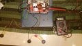
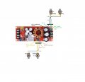
I wired the converter as you told me according to your second illustration please see diagram and photos. and I got BIG Problems.

What is going on with this freeking thing!!!!

First let me say, I wired the board up the way you originally told me and I had control on both the course pots and fine pots on the voltage, it appeared (I could not test it at that moment as I did not have a load available) but it appeared that the CC was also working on both the fine and course pots as it caused the multi meter to dance the voltage, and if I just cracked the power it could be shut off by the fine adjust on the cc.

So I have set it up as you have told me please see diagram below photo 1 ( I believe that I hooked everything up correctly) I originally had a 2k pot for the fine with the 200k pot as course. When I plugged in the power, I received NO adjustment on the fine controls of either the CC or the CV ONLY adjustment was on the course pots. Remembering what you said about how the fine pots don't adjust well at low voltage, and thinking that the 2k pot was just too low, I replaced the 2k with a 20k pot, wiring it up exactly the same way as I took it apart, and I double checked it against the diagram you sent me.

As soon as I powered the circuit as diagrammed the voltage with the voltage pots on 0, and the CC fine pot on 0 with the CC corse pot slightly turned on, the output voltage screamed to 120v and would not come down.
The CV course pot all the way to the CCW position off position When I saw the voltage jump up I immediately disconnected the power and let the voltage drop to normal operating voltage 40v
Thinking that I might have reversed the atunation of the course pot , I turned the course CV pot to the full CW position and plugged in the power again, and again the power screamed up to the 120v range I immediately disconnected the power and let it drop down.

I tried the same procedure I turned the CV pots all the way off and kept the CC course pot full off it kept the system shut down, The moment I cracked the power on, it screamed up to 120v again, I let it power down, and then turned the CC Course pot wide open to verify that I didn't flip the 1 and 3 legs, powered up and screamed up to120 I tried adjusting the CC fine pot at this point and nothing no voltage drop or gain, I pulled the plug.

To verify that the board was working still correctly, I pulled the CC fine a 500 ohm pot and wired it normally, as originally, Please see last photo. This solved the problem with the voltage screaming up, it is now in the normal range. I tried adjusting the CV course 200k and it adjust normally within the designed voltage. BUT I still do not have any adjustment on the CV fine pot 20k

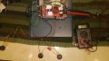
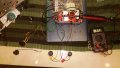
So in recap no fine adjustment on fine pots, with 4 pots (2 course, 2 fine) With the 2 k pot the voltage was in normal range photo 2 and 3
removing the 2k fine pot and replacing it with a 20k pot caused the voltage to scream up to 120v
removing the 500 ohm CC pot causes the voltage to return back to normal still with no adjustment on the CV fine pot. photo 4

What is going on with this flipping thing??? why is it not working????

current wired system.jpg
Fine voltage set to low small dial in middle
fine set to low.jpg

Voltage fine set to high same output voltage small dial in the middle
fine set to high.jpg

CC Course direct wire
cc fine removed with just pot set strait to terminals.jpg


Actually, after giving it some more thought my original drawing won't achieve the fine adjust, all it will do is slightly alter the current in the circuit. The drawing below will do better at giving you a voltage adjustment (not current); which by the way, having the extra resistance wouldn't have given you any more current, it would have reduced the current. So my modification wouldn't have blown up the board. However, if you hooked the fine adjust across the Vcc & Vgg then that could be the reason why you blew out a board. Another good reason for the changes I made to my drawing. Minor changes but no matter what, you shouldn't have blown up a board from my first drawing. You should also understand that when setting to the lower limits the fine adjustment will become less affective whereas at the higher limits the fine adjustment should be more sensitive. Just be sure you never drop the resistance to zero across pins 1 & 3 on the board.

[edit] The new drawing should make it clear how to hook up the fine adjust pot (VR2). This can be on either side, connected to pin 1 (of VR1) or on pin 3 (of VR1). VR1 should be your coarse adjustment and should be wired in place of the original variable resistor that was originally on the board. VR1 should be the 200K and VR2 should be the 2K. If (in my original drawing) you got those reversed then that could account for blowing out the board. Be SURE to follow the drawing, and make sure everything is right before you power it up. If it blows up again - then there's something going on that I'm unaware of.

View attachment 129881
 
Last edited:

Tonyr1084

Joined Sep 24, 2015
9,744
If you have no load on the system while you're working in CC mode then I can understand why the voltage would shoot up to max. In CC mode the voltage will change in order to maintain a constant current. With no load there is no reason to expect to see some kind of variable reading. I'd suggest you try putting some kind of load on the system, be it a light bulb or small motor and see what happens.

And since you're using this to cut foam, I just used my welder and a long length of welding wire. The wire (9 feet long) got hot enough to cut foam using a 24 volt welder as a power supply. You're attempting to do something that I'm not certain will work. Maybe it will, maybe not.

Sorry for not getting back to you before now, I've been in bed with the flu. Summer flu is the worst. I'm only up now because I'm tired of laying in bed 20 hours out of the day.
 

Tonyr1084

Joined Sep 24, 2015
9,744
Oh, and learn to describe things for what they are. There's no such thing as a 25µF diode. Capacitors are rated in Farads, milli-farads, micro-farads (µF), nano-farads and pico-farads. Diodes are rated for their ability to conduct so much voltage and so much current.
 

R!f@@

Joined Apr 2, 2009
10,007
Changing the pot resistance than that of the original will cause adjustment problems.
You cannot replace a 2K with 20K and accept it to work.

Try again replacing with exact pot value with shorter leads.
Forget about fine adjustment pots for now. Try with course adjustment and see if the CV and CC works with a load

A fine adjustment is just inserting a pot by cutting just 1 wire. So leave it and see if the thing works with just 1 pot. Again first use shorter wires
 

R!f@@

Joined Apr 2, 2009
10,007
Further more it could be that the additional fine pot is causing the issue.
Adding a 20K fine pot into a 200K course pot will result in 220K, so if the Pot is in feedback or set by a resistive divider, I dunno what kinda of issue it would cause.

If the pot were used with in a stable reference source, adding a another small pot would be OK. But since this a DC to DC converter and without the actual complete schema we cannot figure out the issue easily
 

R!f@@

Joined Apr 2, 2009
10,007
I am taking it one step further, as most people use only the 120w Ltc 3780 converter, I am using that as well as the 1500w converter to go from 0 up to 85v 0 amps upto 20 amps.
Do not believe that for a mere second that you can draw 20Amps from this.
These are cheap products and very poor design plus not enough cooling.
If it is rated for 20Amps expect half of that at best.

I have used the so called 5A CV, CC supply from china.
I load it to 5A, it over heated and blew. Another cases the rectifier diode shorts.
At best 3A was the safety limit.
Be warned.
 

Tonyr1084

Joined Sep 24, 2015
9,744
I'd have to add that if this is to simply heat a cutting wire then why do you need a fine adjustment? Would seem like you're trying to build a scope for a shotgun. Would LOOK pretty cool, but totally useless in application.
 

Thread Starter

born2dive00

Joined Oct 24, 2016
285
Tony
What I mean by maximum is this, with the blue pots in or wired directly to one 5k and 200k , the maximum voltage is about 87v and it has adjustment up and down immediatly.
As soon as I add the fine pots in via illustration 2, it is basically shorting the system and allowing 0 resistance, and allowing the out put to climb way up past its designed maximum of 87v all the way up to the capacity of the capacitors at about 120v and there is no adjustment at all. even without a load the power should never exceed the 87v at the output, because it is limited by the resistance of the pot and can be increased held or dropped. the load would only cause the voltage to drop faster at a given rate. like on my base station, with all the items on drawing 8 amps I see a drop of 1.1v

Even with a heavy load, it will only drop the output voltage by a volt or 2, it will not account for the difference of nearly 40v without adjustment on the pots.
with using 2 pots as described in illustration 2, it is like they are causing a direct short.


If you have no load on the system while you're working in CC mode then I can understand why the voltage would shoot up to max. In CC mode the voltage will change in order to maintain a constant current. With no load there is no reason to expect to see some kind of variable reading. I'd suggest you try putting some kind of load on the system, be it a light bulb or small motor and see what happens.

And since you're using this to cut foam, I just used my welder and a long length of welding wire. The wire (9 feet long) got hot enough to cut foam using a 24 volt welder as a power supply. You're attempting to do something that I'm not certain will work. Maybe it will, maybe not.

Sorry for not getting back to you before now, I've been in bed with the flu. Summer flu is the worst. I'm only up now because I'm tired of laying in bed 20 hours out of the day.
 

Tonyr1084

Joined Sep 24, 2015
9,744
OK, then don't use the fine tuning pots. You don't need them for what you're doing. If it works without the fine tune pots then go that way. Unless for some unknown reason you NEED an EXACT current or EXACT voltage.

The board you're using is designed to be set up for a certain purpose. When you take it beyond what it was originally engineered for then you can likely expect things to not work the way you want them. Like R!f@@ said, keep the wires short as possible. There can easily be interference from an unknown magnetic source causing the system to fail to operate as designed. Honestly I don't see a need for exact current control to heat a wire and cut styrofoam. A hot enough wire will do the trick. A little hotter will cut a little faster. But if you're varying it by 5 milli-volts (or amps) it's not going to make any human detectible difference.
 

shortbus

Joined Sep 30, 2009
10,049
Tony's scope on a shotgun is headed in the right direction. Did you even look at what people are using for hot wire cutters? They sure aren't doing it with fancy power supplies like you're trying. Switching type supplies don't like this kind of thing. They usually have a built in 'short detection' circuit. Your wire, to a switcher, looks like a short, so it goes into protection mode. Most foam cutters just do it simple, a step down transformer and a dimmer to regulate voltage, a basic AC linear power supply, not a fancy DC switcher.

Just one of the many links from guys that do it every day. http://www.jacobs-online.biz/power_supply_design.htm
 

Tonyr1084

Joined Sep 24, 2015
9,744
@shortbus I like that link.

The way I cut foam was to use welding wire about 9 feet long on a 24 volt (or thereabouts) welder. The wire got hot enough to stretch itself, but a swing arm held taught with a spring took care of the slack. I could cut through an 8 foot panel by 2 inch thick in about 5 seconds. And anytime I had a smaller piece to cut I still used the full length. No need to vary anything. My 9 foot wire was hot enough to cut through foam, whether 2 feet long or 8. Or anywhere between 1 inch and 8 feet.

[edit]

I didn't think a dimmer would work on a transformer.
 

Thread Starter

born2dive00

Joined Oct 24, 2016
285
Hey guys, Tony
1st I don't have a welder, don't have a need for one (most days) and most of the time they are more expensive than a commercial foam cutter.
2nd I have had a lot of spare electronic parts lying around the house that I am using to build this unit.
3rd it is not that I want a fine tune on the boards, it is that I need one, even with the slightest touch on the main course pot, the voltage jumps 5-10 volts if you sneeze on it (WAY TOO SENSITIVE)
4th. Other people have built bench top power supplies and have asked how to put a fine tune pot in it so it is not just me asking.
5th. If you add a 10A X value resistor and switch to the output line right before the plug ins, you can select wether you want the power to run normally bypassing the resistor to enable short detection, or you can select the switch to run the power thru the resistor to stop the short detection. this works well I have done this on many short protected cricuits so far, the over load detection protection will still trip if a short is detected and the voltage total amps goes above the set value you put in with the Vin over load pot, the one that is still on the board.

Tony lets back up one moment to your very first illustration, when I wired this up to the board it worked beautifully, I had course voltage control with the 200k and fine voltage control with the 2k to 1v (this was a little too small ergo I was thinking of using the 20k to get a little more swing) I did not test the CC with the 5k and the 500 ohm pots but I suspect that they were working as they both shut down the power when reaching near 0, and I could read that voltage drop on the meter.

SO what is the difference in the setups between illustration 1 and 2? Could it be that the board is setup to use the system like in illustration 1?? unfortunately there is no schematic available for the 1500w board.

@shortbus I like that link.

The way I cut foam was to use welding wire about 9 feet long on a 24 volt (or thereabouts) welder. The wire got hot enough to stretch itself, but a swing arm held taught with a spring took care of the slack. I could cut through an 8 foot panel by 2 inch thick in about 5 seconds. And anytime I had a smaller piece to cut I still used the full length. No need to vary anything. My 9 foot wire was hot enough to cut through foam, whether 2 feet long or 8. Or anywhere between 1 inch and 8 feet.

[edit]

I didn't think a dimmer would work on a transformer.
 

Thread Starter

born2dive00

Joined Oct 24, 2016
285
A dimmer will work only up to 4 feet and only for a short time and its limit is normally about 12-24v.
I have tired that before. as soon as you try to cut 6-8 feet of foam with 50-80v, it overloads and smokes out.
Also there is wild voltage and amp fluctuations when reaching near the limit. I am talking 15v and 2-3 amps fluctuations. one moment the wire will be glowing hot the next ice cold when trying to cut 4-6' panels. leaving crappy cuts.
This is why I am trying to make this unit.


@shortbus I like that link.

The way I cut foam was to use welding wire about 9 feet long on a 24 volt (or thereabouts) welder. The wire got hot enough to stretch itself, but a swing arm held taught with a spring took care of the slack. I could cut through an 8 foot panel by 2 inch thick in about 5 seconds. And anytime I had a smaller piece to cut I still used the full length. No need to vary anything. My 9 foot wire was hot enough to cut through foam, whether 2 feet long or 8. Or anywhere between 1 inch and 8 feet.

[edit]

I didn't think a dimmer would work on a transformer.
 

Thread Starter

born2dive00

Joined Oct 24, 2016
285
I fortunately have not had bad experiences with these converters on other projects, I have taken the LCT3780 past the recommended continuous amperage of 7 amps regularly on my base station. I have added a cooling fan as per the recommendations above 7 A continuous, they claim that they max out at 10 amps, under continuous use with additional heat sink/fan. having added additional heat sink and fan I took one LCT 3780 to 13 amps input for 45 minutes at I think 12v exceeding the recommended watts of 120w max by 40w. never did burn out.

However I have had the a few 5v mini converters (type they use for the cigarette lighters) and 1 lct3780 burn up in a few seconds due to loads, some as you say R!f@@ with hardly any loads. The new style LCT3780's seem to be damn good and cheap $15 with shipping.
I am curious to see how the 1500w fairs up. I have seen my neighbor here running an electric scooter with one of the 1500w converters, using a 12v car battery boosting the power up to the 48v for the motor@ something like 1400w if I recall and it seems to be going good.

However I do agree with you some things are crap, I guess it depends if you purchase them from the MFG or from a copy cat company.

Do not believe that for a mere second that you can draw 20Amps from this.
These are cheap products and very poor design plus not enough cooling.
If it is rated for 20Amps expect half of that at best.

I have used the so called 5A CV, CC supply from china.
I load it to 5A, it over heated and blew. Another cases the rectifier diode shorts.
At best 3A was the safety limit.
Be warned.
 

Tonyr1084

Joined Sep 24, 2015
9,744
I'm starting to think this is over my head. So I'll share something with you as a parting word. Hopefully I'm not coming off like I think you're not smart enough, obviously you are smart enough to have gotten this far.

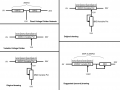
The drawing below shows a fixed voltage divider network with an example of a 20 volt supply. The ZERO end is the ground or negative leg of the divider. Between the two resistors is the tap off where five volts are dropped across the first resistor and the other 15 volts across the higher value resistor. This is how you set a reference point for the op-amp(s) to decide whether to boost or cut power to the circuit to maintain your desired voltage. Below that is a single potentiometer with its wiper set about 3/4 toward the high end and is giving you the same 15 volts out. Of course you can change the location of the wiper by turning the knob and thus change the reference voltage for the op-amp to keep the circuit in check. The third drawing down shows the first drawing I provided. With the wiper in the same position you can see that the voltage is still sitting at 15 volts. Why? Because resistors don't resist voltage they resist current. And in this configuration you need to vary the voltage and not the current.

Over on the right side is both drawings, the first being on top, again, showing no change in voltage at the output (the downward line). The second drawing shows you the way I recommended you go, and still recommend. When you change the fine tune pot you make very very small changes, and that's the fine tuning you want. Depending on where the fine tune is set you'll increase or decrease the voltage coming out at the bottom. I can't explain it any simpler. Maybe someone else can.

I think I've done all I can do to help you. The problem may lie in the length of the wires. However, if you prefer using the first setup - you have it again (top right drawing). If it worked for you then for reasons I can't explain - it worked. MAYBE adding the 2KΩ pot in series (bottom right) sets the voltage too far away from where the op-amp is expecting to see a voltage. Maybe you need to modify the board (don't ask me). I'm just guessing now.

I hope you solve your problems. Too bad they don't make a 198KΩ pot. The circuit may prefer to work with 200K, and 202K is just outside the parameter it will work with.

Good luck.

Variable Voltage Divider.png
 
Last edited:

Thread Starter

born2dive00

Joined Oct 24, 2016
285
Tony I thank you for all your help with this, and I hope you get to feeling better soon.
Is it possible that board is look looking for current shifts rather than voltage shifts? my suspicion is yes.
is it possible that what we are assuming as ground leg 3 is not ground and it is 2 that is ground? (this would explain the uncontrolled voltage spikes no?)

When I get home I am going to verify the new drawings against the way I have it laid out. If I have it laid out correctly and it still does not work, I will try the first drawing again but with the 20k pot to get more adjustment on the low end. and I will do a load test, I have a nagging suspicion I now know what is going on.

My nagging suspicion is that the board is looking for current fluctuations (illustration 1) and not voltage fluctuations (illustration 2), Ergo why the first drawing worked and the second is not. this could also explain what they mean by "automatic lifting constant" voltage step up down.

I compared your second illustration you sent to another drawing that was given to be by someone at the electronics. They were the same. I connected his drawing (this was before I saw yours) and it immediately burned out the LCT3780 board.

If all else fails I suppose I can get a 5 or 10 turn knob pots and use them (Crank crank crank lol), I don't like them but it should work. just solder and go.

You have given me great help Tony and I will keep you apprised of what develops.

.


I'm starting to think this is over my head. So I'll share something with you as a parting word. Hopefully I'm not coming off like I think you're not smart enough, obviously you are smart enough to have gotten this far.

The drawing below shows a fixed voltage divider network with an example of a 20 volt supply. The ZERO end is the ground or negative leg of the divider. Between the two resistors is the tap off where five volts are dropped across the first resistor and the other 15 volts across the higher value resistor. This is how you set a reference point for the op-amp(s) to decide whether to boost or cut power to the circuit to maintain your desired voltage. Below that is a single potentiometer with its wiper set about 3/4 toward the high end and is giving you the same 15 volts out. Of course you can change the location of the wiper by turning the knob and thus change the reference voltage for the op-amp to keep the circuit in check. The third drawing down shows the first drawing I provided. With the wiper in the same position you can see that the voltage is still sitting at 15 volts. Why? Because resistors don't resist voltage they resist current. And in this configuration you need to vary the voltage and not the current.

Over on the right side is both drawings, the first being on top, again, showing no change in voltage at the output (the downward line). The second drawing shows you the way I recommended you go, and still recommend. When you change the fine tune pot you make very very small changes, and that's the fine tuning you want. Depending on where the fine tune is set you'll increase or decrease the voltage coming out at the bottom. I can't explain it any simpler. Maybe someone else can.

I think I've done all I can do to help you. The problem may lie in the length of the wires. However, if you prefer using the first setup - you have it again (top right drawing). If it worked for you then for reasons I can't explain - it worked. MAYBE adding the 2KΩ pot in series (bottom right) sets the voltage too far away from where the op-amp is expecting to see a voltage. Maybe you need to modify the board (don't ask me). I'm just guessing now.

I hope you solve your problems. Too bad they don't make a 198KΩ pot. The circuit may prefer to work with 200K, and 202K is just outside the parameter it will work with.

Good luck.

View attachment 129977
 

shortbus

Joined Sep 30, 2009
10,049
A dimmer will work only up to 4 feet and only for a short time and its limit is normally about 12-24v.
Did you read the link I gave earlier? The one Tony liked? Still don't understand your insistence on this wire cutter using DC, when most of them are using AC, and this is both the store bought and home made hot wire cutters. I'm pretty sure (without knowing it myself) there is a reason behind them using AC on the actual cutting wire.

On second thought maybe I do know why they don't use a switcher power supply. Probably the same reason they don't suggest them for stepper motors. It's the very small output capacitors, compared to a linear type power supply. The larger, much larger output cap in a linear supply gives the output more 'headroom', more available power between the rectified DC pulses. Switchers work great and are good for what they're made for, but there are things they don't work good on.
 

Tonyr1084

Joined Sep 24, 2015
9,744
I haven't read this entire thread but it may be possible to improve stability by adding some resistance in series with the cutting wire so that the PSU never sees a short-circuit.
The OP would have to use a very high wattage resistor. Trying to use a 1/4 watt or 1/2 watt, anything under 10 watt may burn up. It all depends on the wire resistance as well.

At a hardware store that was going out of business in Ely Nevada I bought a multi-tapped (doorbell) transformer with a common, 8 VAC, 16 VAC and 24 VAC outputs and I got it for a couple dollars. I have (and posted about this transformer before) a transformer out of a dead stereo. It has three secondary outputs. One at 5 VAC, one at 24 VAC with two multi taps with 12 VAC between them and one center tapped at 65 VAC. I also have several other transformers that came from different projects, so using an old transformer is VERY easy to acquire. I even have a couple micro-wave oven transformers. So any hobbyist would likely have a few (at least) transformers available for experimentation. Light dimmers are cheap enough. If all someone is doing is cutting foam I think this would be the way to go. Heat up the wire just hot enough to cut one inch (thickness) every two seconds and the wire will likely never glow red hot. If it's glowing red hot then it's TOO HOT.

But hey! The OP wants to do it his way - I say "let him."
 
Top