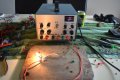
Why when I Replace the PCB pot with manual pots, the manual pots wont work when correctly wired

Thread Starter

born2dive00

Joined Oct 24, 2016
285
I am cutting main wing core blanks for a plane, each of the 3 wing segment is 65" long and up to 18" wide, and up to 4" thick (and can not be cut smaller due to structure issues) I am using High density styrofoam pallets this Styrofoam is about 5 times the density of normal Styrofoam and a pallet can hold nearly 2 tons of weight, so the weight to strength is phenomenal. You can use either use a 2oz glass and fly it as is, or you can cover it with epoxy and PVA and make a fiberglass mold of the perfect wing without having to do a lot of finishing. (similar to the old school vets and porshas making the body out of clay then making a mold of the part to make the final part.)

As far as the circuit board I fully agree with you on soldering and de soldering electrical items on a board. I have burned the traces in the past from pumping too much heat on them due to solder de soldering (I agree with you 3 times is the most) This is why I use a solder wick (sucker) and solder header pins on only 1 time when I am experimenting to prevent heat damage.

As far as the damage to the board It seems like it is working fine, however I have purchased 3 more LCT 37802 and 1 more 1500w converter just in case.
The purpose of this power supply is dual purpose 1st a hot wire cutter, then 2nd as a bench power supply that I can use for testing solar systems, and the small converter for using on small electronics. The biggest reason that I am trying to get the fine to work, is on the course if you sneeze on the knob when adjusting it jumps 5-10 volts. and the amps jump +- 3A with using just dial knobs. This screws with the heat on the wire.

The biggest reason I want to use this is with constant current, it is pressing the same voltage/amps without regard to load. i.e. if no load it is (for an example 65v and the amps will drop to XX value. Once a load is placed on it, the load will want to drop the voltage and current down. Using a CC supply it will automatically jump up the voltage/amps to what you have set them at. and will keep the wire hot all the time. No need to worry about the air temp vs the load temp. and no need to adjust between voltage/amps when cutting different widths.

With CC once you set the voltage and current the unit automatically adjust depending on load. Once set it will automatically keep the wire at 600 degrees +-15. No worry about hot spots cold spots.

If you look at most of the youtube videos of people cutting a Styrofoam wing, when they finish the cut you will hear a twangggg like a guitar string or a pop (this is because they are trying to cut with pressure because the wire is too cold). This is what causes a jagged cut, think of a sharp knife vs a dull knife and a tomato.

When you cut foam perfectly there should be no sound coming from the wire on the draw, no sound when the wire exits the cut. it should be smooth and silent. with a 30g wire I can get a uniform cut over 96" with less than .005 of an inch. and this diviation is more often to me having to reposition the cutter or a mistake when I cut the guides.


But I have to imagine (and by imagine I mean I have no practical experience with this) whether the wire is 550˚ F or 650˚ F, you should still get a pretty good cut. If time is such a factor then again, I'd opt for the bigger bucks machinery. It's your project, build it as you see fit.

If after you've finished your cutting and you want to repurpose this device - I can understand wanting to have the fine adjustment working.

Somewhere in the circuit there must be a "Sense" circuit. For a fine control you could isolate that part of the circuit and set up a fine adjust pot across the reference voltage feeding an op-amp (or comparator). But now you're working at circuit level where you need to know the reference voltage and how it's achieved.

Whatever you come up with, good luck. I hope it gets working for you. But I wouldn't discount the notion you may have hurt the circuitry already with all the heat and testing you've (probably) done.
 

Thread Starter

born2dive00

Joined Oct 24, 2016
285
1st that it can be done.
2nd from what I have read, no one has (based on my research or no one has posted how to do it) done it with these circuits
3rd because many people out there have been asking how do you add a fine trim pot to a circuit board like this for a bench top power supply.

Im checking the traces again

Hi,
May i know what is your trying to prove by doing such idea.
Second see in schematic drawing (if you have it) where this pot is going inside the circuit.
You may changing the required resistance as it in original this will cause not to work the oscillator circuit.
 

JUNELER

Joined Jul 13, 2015
183
Hi,
what really you want to get on this idea,and to prove something.
if you dont have a schematic circuit,do a reverse engineering of the circuit.
The pot resistance and the wiring may cause the oscillator circuit not to work if it is smps power supply unit.
 

Thread Starter

born2dive00

Joined Oct 24, 2016
285
tAlec, Tony,
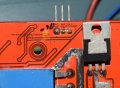
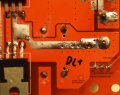
I just checked the traces again please see photos below. PINS 2 and 3 ARE connected together!!! Photo 1 shows the topside (front of the circuit and on the CC you can see where pins 2 and 3 are connected

The second photo shows the CC back side again you can see pins 2 and 3 are connected and they have a common continuity to DC - Output
Pin 1 is power with 4.9v

The third photo shows the CV back side, you can see where pins 2 and 3 are connected by a very small tracer. Pins 2 and 3 have a common continuity to DC +
pin 1 is power with 118v

So WITH PINS 2 AND 3 CONNECTED WOULD THIS NOT BE ACTING AS A RHIOSTAT????

Please let me know! please expand to full screen to see my notes I made on the photo

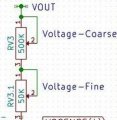
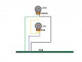
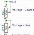
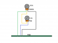
Which setup is correct for adding a coarse and fine pot, this

FGRIY4IIQYSYIHV_LARGE (2).jpg I realize I have to replace the pots with proper size. OR this Coarse N Fine Pots (2).png

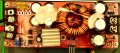
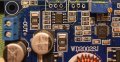
1500w converter top side.jpg CC pot back with continuity test DC-.jpg CV pot back side and continuity test DC+.jpg


Have a good look at the pcb tracks. Are pins 2 and 3 connected by a common track (possibly right where the original pot attached to the board)?
Yeah, I'd agree with that. The cutting I did was on sheets two inches thick, four foot by eight foot. I always cut through the two inch dimension. In such a short cut I didn't see any waves. I cut my foam to fit into a basement room to act as sound proofing so that when I played music it wasn't bothersome to the people up stairs. (by the way, it's not a very good sound insulator)

I can't imagine where you're getting blocks of styrofoam (styrofoam is what I cut, but I suppose you could cut foam rubber and the likes too) 96 inches long by 48 inches thick. I'm sure it's out there. But if you're cutting this stuff then it's got to be for some sort of mass production. In which case I'd opt for the bigger bucks to get a machine designed specifically to do what you're wanting. But I still wonder why you need to control the current so precisely. A hot wire is all you need. TOO hot and you can run into problems. Too cold and you're going to get an ugly cut (as you said). But I have to imagine (and by imagine I mean I have no practical experience with this) whether the wire is 550˚ F or 650˚ F, you should still get a pretty good cut. If time is such a factor then again, I'd opt for the bigger bucks machinery. It's your project, build it as you see fit. If after you've finished your cutting and you want to repurpose this device - I can understand wanting to have the fine adjustment working.

Somewhere in the circuit there must be a "Sense" circuit. For a fine control you could isolate that part of the circuit and set up a fine adjust pot across the reference voltage feeding an op-amp (or comparator). But now you're working at circuit level where you need to know the reference voltage and how it's achieved. Not too long ago I modified a power supply from an old satellite power supply. It put out 12.05 volts but I wanted 13.6 volts. It wasn't a difficult build and I got a lot of help with it right here. Many of the people answering your questions are the same who answered mine. My repurposed circuit is out in the garage running as expected.

Whatever you come up with, good luck. I hope it gets working for you. But I wouldn't discount the notion you may have hurt the circuitry already with all the heat and testing you've (probably) done.
 
Last edited:

Thread Starter

born2dive00

Joined Oct 24, 2016
285
So the previous photos were for the 1500W converter

The next set here are for the LTC 3780 in the first photo which it shows the CV pins 2 and 3 are connected together and the trace goes to DC-
pin 1 is the power pin.
So since pins 2 and 3 are connected together, the 500k pot that was there was setup as a rheostat correct??

I believe this photo is correct but CAN SOMEONE Please tell me if this drawing is correct to add a coarse and finepot to the CV?FGRIY4IIQYSYIHV_LARGE (2).jpg OR this Coarse N Fine Pots (2).png

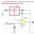
Can some one tell me how to wire a course and fine pot to the CC.
CC pot diagram.jpg Supposedly this is the schematic of the CC circuit on the LCT3780


The green lines are the traces on the front, the red lines are the traces (from what I can tell) on the back of the board
LCT 3780 Front traces.jpg LTC 3780 Back .jpg LCT 3780 Front traces.jpg LTC 3780 Back .jpg
 
Last edited:

shortbus

Joined Sep 30, 2009
10,049
Again not to belabor the point, but all of the industrial and CNC cutters sold by any reputable or for that matter any firm selling them use AC for the wire. Doing a quick Google search will show you that.
 

Thread Starter

born2dive00

Joined Oct 24, 2016
285
Yes they use ac up to the transformer, but the power on the wire is DC. They run the ac voltage thru rectifiers just before it hits the wire. I have been why do you think they use DC digital meters on the amps and voltage? how are they going to get a accurate read on a meter if using ac? they cant. The ac gets converted from high ac to low ac, then rectified, then either bind the terminals to increase the voltage then use a DC motor controller for output OR they use (more commonly) a buck boost converter. I tell you what Shot bus, you go ahead and buy a from these guys. http://www.shop.hotwiredirect.com/index.php?main_page=index&cPath=39_40 any one you wish, The wires according to the MFG are on DC. Any professional in the industry knows that and will tell you that dc cuts better. More over, you said (I believe you said) that you use 24v to cut large sheets. HOW is this possible when a standard 30g nichrome wire 96" long takes 65v @ 1.2A to get the wire evenly hot, if you apply 24v at say 4 amps the one end of the wirer will get hotter and (in some cases) melt or in other cases explode when cutting.

So do as you wish, p.s. I have toured 3 of the local hotwire power supply mfg companies when I traveled in Taiwan all the companies say DC. Oh and they Mfg over 80% of the industries hot wire power supplies.

The Switching power supply I am using here Short bus is only for the testing of the circuits. I never said I was going to use this for the final power supply. In fact I am planning on using a 1kva 120- 12 isolation transformer I am building.

Again not to belabor the point, but all of the industrial and CNC cutters sold by any reputable or for that matter any firm selling them use AC for the wire. Doing a quick Google search will show you that.
i
 

Thread Starter

born2dive00

Joined Oct 24, 2016
285
Hey Short bus, IF you can read, you just shot yourself in the foot!
You just contradicted yourself when you said “where does it say DC”
In your very first link, the very first paragraph it says

"For years our recommendation has been to purchase a commercially available DC power supply for use on all hobby hot wire foam cutters. Not only this, but to specifically shy away from any AC power source and/or creating your own power supply using a doorbell transformer (which is a AC Step Down Transformer)."

If you continued to read your first web page you linked to, it says and warrens about how ac is more dangerous than dc.

Please continue reading I will try my best to explain the safety of the design of AC vs DC, Shor Bus you know a lot about the theory of electronics and what things do what. I respect that fully and thank you when you help me out with questions on circuits..., But I know a lot on the designing systems, safe systems.

Shortbus there is a lot of information you should read fully here. But if you don’t wish to read the whole thing, please feel free to scroll down and read the last 8 points and my final message to you.

The AC is more dangerous on 2 accounts 1st as everyone know if you get shocked with ac it can kill you, Why (the over simplified reason) is that the alternating waves of the AC screw with the endocrine system, (you know the system that controls the heart, breathing, and the brain) it will stop the electrical activity killing you. When does this happen, in theory if the ac voltage is above 12volts. but most people can take a hit of 24 volts with a sharp tingle, or at 48v leaving your hand and arm numb.

Second reason is AC cooks the muscles (think microwave oven) and nerves causing damage to the nerves in the hand or any other body part, this is can be sever and instantaneous.

Dc and the body, basically your body is a large dc battery, ergo introducing dc voltage into the body (while not good) is less likely to cause damage to the endocrine system. If you have ever gone to the chiropractor and he puts those pads on your back (or at home with a TENS) machine you are subjected to dc voltage at about 60-200vdc@ .05-1A. at very high voltage it causes the muscles to spasm or hand will clench closed as soon as the power is released the hand returns to normal without any pain after words.

At very extremely large voltage and amps on dc voltage, like a lightning strike it burns the outer skin (while it damages the nerves) it is temporary until the skin heals (this is why many people who get struck by lightning survive the ordeal with surprising little ill effects of the strike considering the amount of voltage and current that went thru them. If a strike of the same power as a lightning strike hit them but was AC current, they would be baked inside and out not to mention dead.

This is why you can touch the live electrode of a welding stick at 18-100 vdc at 1-5 amps ( and yes some welders can go this high) and touch the metal part you are working on and not get killed. (shocked perhaps) dead rarely.

Concerning your remark about the transformers YES in the your first post they show are indeed AC BUT if you look are limited to 6 and 12vac which limits the cuts to a short 30-40" long cut.

Jacobs online sells transformers their biggest power supply http://www.jacobs-online.biz/transformers.htm#XFR3024E for the "hobbyist" have a maximum output voltage of 24 and 48 volts. They limit the ac voltage to 24 and in some cases 48vac, why? So people don't get electrocuted on the AC. Their largest power supply on 24vac can only cut up to 100" with a MONSTROUSLY THICK 16g wire and on 48vac it can only cut up to 130" with a VERY THICK 20g wire.

Both of these wires are WAY too thick to get clean accurate cuts. You must have higher voltage with a thin wire.

For a nice narrow kerf you need to use a 30g wire that is 96" long. to get to 600 degrees (normal cutting) you must apply 65volts at 1.2A. to get to 800 degrees for coarse/ fast cutting you must apply 80v @ 1.5A Take a look at their calculator here. http://www.jacobs-online.biz/nichrome/NichromeCalc.html

So we need high voltage to use a long wire to make narrow fine cuts.

This brings us to your second link, Really Short Bus??? I know you didn’t just recommend an AC Variac as a industrial power supply nor as good power supply for hobbyist!!! ARE YOU NUTS!!! Are you Trying to kill yourself or others!

You do know that a variac is pole sensitive don’t you? (I will explain for those who will look at this post) a variac is pole sensitive, so if you plug it in to the wall one way and turn it full left to the off position it should be off, leaving it in the off position and just flipping the plug over and plugging it back in the wall what was full left off, is now full left on! If you don’t pay attention you now have a live hot wire running 120v or 240v (depending on your setup) now if you touch that wire you are now dead.

This is not to mention if you pump 120v thru most wires it will blow the wire instantaneously! Melting it at the very least, at the worst exploding the wire sending hot metal slag all over the place.

The other point is the fuses on a variac are not reliable, If the wire melts off, the wire is still electrically charged. If this finds a ground on anything metal or on something damp it will conduct and start a fire. Not to mention if you grab the wire and the fuses have not blown (reason is you are drawing 1-5 amps the power supply to the variac and the variac are fused at 10-20 amps, so it will not always blow the fuse) you will get shocked with what ever the voltage is set at and up to the fused limit of the variac. THIS IS POTENTIALLY DEADLY!!!

PLEASE FOLKS DO NOT USE ONLY A VARIAC FOR HOT WIRE CUTTERS. You MUST use an isolation transformer with a fuse that is near the amperage you are using + 10-25%. The fuses values must be changed every time you change the length of the wire OR change the voltage because the amperage will change. DON’T LET ANY ONE TELL YOU OTHERWISE!! Your life, family and house depends on you doing this.

With an isolation transformer in conjunction with a variac, this will (in theory) cut the voltage off at the isolation transformer if there is ever a short preventing a fire and hopefully a shock.

In that arises another problem every time you adjust the voltage or the length of the wire you must manually calculate the amperage that will be drawn to obtain the correct fuse. And this will only be an estimate depending on the load, density of the media, and air temp. To my knowledge there is no cheap bolt on digital voltage amp meter for ac to let you monitor outputs. You could use 2 multi meters one for amps one for volts on the line but this is difficult to wire up.

Another important safety feature that should be installed is a foot controller connected to a relay that can handle the loads. So that when you take off the pressure on the foot controller it shuts the power down coming out of the variac to the isolation transformer.

Yet another item needed is a AC motor controller with appropiat size for your loads. This should be put as close to the cutting wire as possible to let you adjust the temp of the wire while in the cut, which affects the speed of the cut.

If these problems are not enough, you must have a laser thermometer that you can point at the wire at the beginning of the cut each time to get the temp, adjusting the temp up or down as needed with the AC motor controller. You can not set the temp of the wire while it is in open air for as soon as you put a load on it, it will drop the temp of the wire

Short bus, as far as your third post, look at the size of the foam they are cutting. Short lengths. So 12-24vac is fine as it wont give you a shock. If you look at the nichrome calculator here http://www.jacobs-online.biz/nichrome/NichromeCalc.html and set the temp range to 800 (which is a very hot wire) degrees and you set the voltage to 12 volts. You will see that a 30g wire can only cut 14.5” @1.47A, a heavy duty 22g wire can only cut at 30” @4.5A

If you set the voltage to 24 volts @ 800 degrees then a 30g wire will cut at 30” @1.47A and a heavy 22 gauge wire will cut at 60” 4.5A

How long of lengths did I need to cut again? Oh yah 96” so nothing in the hobbist range of 12-24 volts will work.

Even at 48volts a 30g wire will only cut up to 57” a 22g wire (which is very thick) can cut up to 122” @ 4.5A. So though using a 22g wire at 122” is possible on 48vac, it does not leave you much room to maneuver a 96” sheet of foam to do curved, circles, or anything other than a strait line.

1st It is safer, there is lesser concern for electrocution and fire
2nd It is simpler no need to calculate fuse loads, for changing fuses with each cut, wire temps…
3rd There are more tools/ instruments available for fine tuning
4th With a CC power supply there is no need for the guessing of what the temp of the wire is while it is in the cut, you simply set it and forget it because it will automatically adjust the current and voltage.
5th You don’t need all the “Extra” safety equipment
6th Because you don’t need all the extra junk it is easier to set up dc rather than AC
7th Because you don’t need all the extra junk it is cheaper to set up
8th. Weight savings is also another consideration, with using a Variac and an isolation transformer, yes you can get the high voltage needed but at a cost of weight. With just a step down converter from 120 to 12v you save the weight of the variac which depending on the unit can weigh 20-60lbs. The buck boost converters X2 one for low voltage one for high weigh a whopping 8 ounces. And you still get the same voltages and can fine tune the current to boot. That is a weight savings of between 19.5 and 59.5 pounds you don’t have to move around and your work table does not have to support.

So you see if you have done YOUR research Short Bus you will have read in the very first line that the commercial heavy duty units that can cut larger than 48” ARE indeed DC voltage for the various reasons stated above.

But Hey if you are happy to use power strait from a variac without proper setup, when you zap yourself dead, I will buy your grave stone and these words will be inscribed.

I warrened him it was unsafe, he refused to listen,
Steadfast in his belief, now he helps the grass to glisten


shortbus

Joined Sep 30, 2009
10,049
Hey Short bus, IF you can read, you just shot yourself in the foot!
You just contradicted yourself when you said “where does it say DC”
In your very first link, the very first paragraph it says

"For years our recommendation has been to purchase a commercially available DC power supply for use on all hobby hot wire foam cutters. Not only this, but to specifically shy away from any AC power source and/or creating your own power supply using a doorbell transformer (which is a AC Step Down Transformer)."
I know I'm never going to change your mind. But if you want to talk about reading comprehension, don't cherry pick from that first link of mine. Did you read the large print of that link just after part you quoted? The part that said,
"So rather than provide unreliable and unsafe options, we have always taken the stance to recommend commercially available DC power supplies which were safer to use. UNTIL NOW!!" They then link you to Jacobs, (which I first told you about earlier in this thread) that sells AC transformers not DC power supplies. There are many CNC type machines out there by companies that have supplied them to industry for years, and they all use AC not DC. But I'm sure any of those companies finding this thread will soon see the error of their ways, and convert to your way, and soon if they're smart.

You trying to bring back the Edison vs Tesla electric wars is just ridiculous. I also still stand by my statement the watts are watts, AC or DC, and watts are what will get this cutting done. And your saying a thin wire will cut more precise than a thicker one is just untrue. But YOU win! I give up.
 

Thread Starter

born2dive00

Joined Oct 24, 2016
285
Jacobs sells AC transformers True BUT ONLY UP TO 48vac which will never cut a sheet of foam larger than 60" to get longer cuts you have to increase the voltage. My point is that AC at higher voltage is more dangerous than DC. This is the reason that neither your first page nor Jacobs sells AC transformers larger that 24-48 volts to HOBBIEST. vs Anyone can and should build a buy and use a high power DC power supply for hot wire. it is safer and easier on so many levels. as far as me saying implying a thinner wire is gives a more precise cut, it is very true a thin kerf does give a cleaner smoother and more accurate cut simply due to higher tension over a smaller area keeps the line tighter and prevents sag when it gets heated.
A properly tensioned when heated, should have not more than .005 of a variation anywhere. expecially at the center point of the wire.
The thicker the wire like 20g the more tension that is needed to prevent sag. most people think that the diameter to strength ratio doubles every time the square mm of the wire doubles when in actuality it is only about 1.25.

So what this means if you have a 20g wire you can not stretch it hard enough cold or hot without breaking it to prevent sag under its own weight. This is why a 20g wire will very often have about .010- .050 variation between the ends and the center.

The reasons I have very clearly detailed out there, and why the industry HAS and CONTINUES to use DC voltage on systems where the person may come at risk of touching a live wire.

CNC technology generally does not have much risk of the operator coming into contact with the working head unless changing the tool. and even then the system is shut down and locked out.

Can AC be used safely, depends on the setup for cnc applications sure. for manually manipulated user controlled systems should it be used NO.

You and I are trying to compare apples to oranges here Short bus. so as you said I am done with it too.
But I still love ya, we just have different applications that require different tools.

I know I'm never going to change your mind. But if you want to talk about reading comprehension, don't cherry pick from that first link of mine. Did you read the large print of that link just after part you quoted? The part that said,
"So rather than provide unreliable and unsafe options, we have always taken the stance to recommend commercially available DC power supplies which were safer to use. UNTIL NOW!!" They then link you to Jacobs, (which I first told you about earlier in this thread) that sells AC transformers not DC power supplies. There are many CNC type machines out there by companies that have supplied them to industry for years, and they all use AC not DC. But I'm sure any of those companies finding this thread will soon see the error of their ways, and convert to your way, and soon if they're smart.

You trying to bring back the Edison vs Tesla electric wars is just ridiculous. I also still stand by my statement the watts are watts, AC or DC, and watts are what will get this cutting done. And your saying a thin wire will cut more precise than a thicker one is just untrue. But YOU win! I give up.
 

bertus

Joined Apr 5, 2008
22,992
Hello,

Are you bound to use the Jacobs transformers?
Perhaps you can get hold of transformers that are designed for audio amplifiers, like the transformers from ILP.
They have transformers that go upto 55+55 Volts.

Bertus
 

Attachments

shortbus

Joined Sep 30, 2009
10,049
Hello,

Are you bound to use the Jacobs transformers?
Perhaps you can get hold of transformers that are designed for audio amplifiers, like the transformers from ILP.
They have transformers that go upto 55+55 Volts.

Bertus
Hi Bertus, he is unwilling to use an AC transformer. Claims they will not cut or heat the wire sufficiently, he also claims that only DC will heat a wire for the full length of it. But every company selling hot wire cutters other than for small hobby/craft projects are powered by a step down transformer.
 

Thread Starter

born2dive00

Joined Oct 24, 2016
285
Hey Bertus

The reason I wanted to use a buck boost converter or a boost converter is I need a wide range of power from 2v all the way up to 80volts.
With using just transformers you can not get the ranges needed usually they are pre set or sometimes they have several coils, that you can connect to get voltages (usually in 12v increments) with a buck boost you get constant pressure regardless of the load, and you have an infinite voltage range.

I am not stuck on Jacobs transformers at all. I am stuck on how to get a wide range of voltages.

Hello,

Are you bound to use the Jacobs transformers?
Perhaps you can get hold of transformers that are designed for audio amplifiers, like the transformers from ILP.
They have transformers that go upto 55+55 Volts.

Bertus
 

Thread Starter

born2dive00

Joined Oct 24, 2016
285
Show me an automatic constant current ( a unit that automatically senses and adjust the current and voltage) buck boost AC converter that can adjust from 2v to 90v and has up to 10 A output, I will happily use AC current!


Hi Bertus, he is unwilling to use an AC transformer. Claims they will not cut or heat the wire sufficiently, he also claims that only DC will heat a wire for the full length of it. But every company selling hot wire cutters other than for small hobby/craft projects are powered by a step down transformer.
 

shortbus

Joined Sep 30, 2009
10,049
Show me an automatic constant current ( a unit that automatically senses and adjust the current and voltage) buck boost AC converter that can adjust from 2v to 90v and has up to 10 A output, I will happily use AC current!
Show me the reason you think this is necessary. I think you have relied too much on postings on the RC plane sites as being the end all be all in this. Sure low voltage DC is what the craft cutters use, due to those people doing small projects, not understanding electricity in general and product liability to the general public. But your not doing something small, your on the scale of industrial. While others don't waste their time wondering about it and just do it. The 'automatic constant current' thing is laughable. Just make a experimental cut and set the out put for the best value. Go back to the Jacobs link I originally showed, and see how its done in the real world.
 

Alec_t

Joined Sep 17, 2013
15,149
I query why constant current is the chosen mode? After all, if you cut agressively and draw excessive heat from the wire then the wire will cool down. Since heating wires have a positive temperature coefficient of resistance the wire resistance will drop as it cools. If the current is kept constant then the I^2R heating will also reduce, making further cooling likely. I would have thought you needed to boost the heating instead, to maintain a steady wire temperature. Hence increasing the current would be desirable IMO. That could be achieved by using constant voltage rather than constant current.
 

Thread Starter

born2dive00

Joined Oct 24, 2016
285
Hey Alec, this is where the buck boost converter comes into play.

It automatically increases BOTH the current AND the voltage at the same time, within the set limits you programed into the unit.
It does not drop only one or the other. it pushes both to maintain preset levels.

Think of it this way you have 3 H3 12v @ 4.8A(55 watts) halogen bulbs, a transformer, and a rheostat.

If you have just a transformer putting out 16 @ 7 amps,

First if you apply 16v of power at 5A the bulb will exceed the recommenced 55 by 25w, and will be very bright (shortening the life of the bulb)

The only way to reduce the power to 12v is by using a rheostat between the transformer and the first h3 bulb. This will manually decrease the power in exactly the same way as reducing the CC on a buck boost pot.

If you apply the 12v to the first h3 bulb (this will represent the wire in the air without any load) the h3 bulb will shine very brightly you are at 12v and the maximum amperage about 4.8a the bulb desires to use at that voltage . Correct? in this case the voltage does the work and carries the amps at 55w of power

Now if you put in series the second H3 bulb (this one represents the load in the cut) AND If you have not adjusted the power on the rheostat and are running 12v what happens? Both bulbs will dim down until the current is balanced between them correct? 55w/2 = 22.5w per bulb.

So now if you adjust the rheostat to full power 16V@7A the bulbs will shine full power 16x7-105w (or near enough) In this case the amperage does the load and carries the voltage. correct?

So now if you forget to reduce the power on the rheostat as you approach the end of the cut, all of a sudden that 55w bulb will be using 35w, then 20w then 10w then 0w and it will apply 16v@7A to only the first H3 bulb, what happens?? It will send 105w of power to the bulb the bulb will use about 80w of power shining extremely bright and perhaps, (maybe not the very first time but eventually) it will burn out the bulb.

Now lets say you have a massive load 5 (in total 1+4) you ramp up the transformer to say 72v@5 A the bulbs will still work but as soon as you start removing the load (because more wire is being exposed to the air getting hotter), (220w down to 110w, to 55w to 10w to 0w on the load,) remove the load and forget to dial down the rheostat, you will be sending 75v to a 12v bulb, what will happen? If you are lucky it will burn the bulb out in a spectacular flash, (in the case of a hotwire, it will melt or sometimes explode)

Now lets say you have your system set up for a heavy load, but can not be bothered to adjust the long wire shorter or to reduce the power because you are lazy. So you have it set up for 800 degrees on a long wire with high voltage, the temp is the wire? It will exceed 800 degrees, probably closer to 1100 degrees. Now you decide to cut a 1” wide piece of foam, what is going to happen probably burn the foam at worst, and make an uneven jagged cut at best.

This is why so many hobbyist complain that their wires don’t last long and they get jagged cuts chainsaw cuts at the end of their cuts when using the 800 degree mark. As the wire pulls out of the foam, the part of the wire that is in the air starts to heat more than the wire in the cut. And the wire being conductive will try to balance out the heat.

This also why when you watch so many DIY systems, when they make the cuts, they are hauling hard on the wire and at the end of the cut you hear twangggg. Why? Because to avoid the jagged cuts at high temps,800 degrees, they keep the wire cooler to get a smoother cut relying on pressure and lower heat to keep the cut clean.

Now if you take and put in a 12v 10A transformer, remove that rheostat, and put in a buck boost converter it will automatically adjust to your presets.

If you set the presets to the recommended voltage and amps suggested by the wire mfg, into the buck boost converter, when there is no load on the system the wire will be 800 degrees, the moment you put a load on the wire it automatically adjust no matter what the load is large or small it will automatically adjust.

With a buck boost converter you can set an infinite values, say you want 1v@ 10A you got it 87v@3A you got it, or 13.4v @100ma you got it.

With the listings of buck boost converters they say constant current, what they are really saying is that the amps and volts will be adjusted automatically to make a stable output within the presets. This is done by adjusting the voltage to create a constant amp current that is independent of the voltage but part of the voltage at the same time.

current limited by voltage high.JPG
Current limited by voltage

voltage limited by current.JPG
Voltage limited by current

The greatest benefit of a buck boost converter is the automatic power output regardless of load. wether that is 1"wide foam or 100" wide foam.


I query why constant current is the chosen mode? After all, if you cut agressively and draw excessive heat from the wire then the wire will cool down. Since heating wires have a positive temperature coefficient of resistance the wire resistance will drop as it cools. If the current is kept constant then the I^2R heating will also reduce, making further cooling likely. I would have thought you needed to boost the heating instead, to maintain a steady wire temperature. Hence increasing the current would be desirable IMO. That could be achieved by using constant voltage rather than constant current.
 

bertz

Joined Nov 11, 2013
327
Hey Alec, this is where the buck boost converter comes into play.

It automatically increases BOTH the current AND the voltage at the same time, within the set limits you programed into the unit.
It does not drop only one or the other. it pushes both to maintain preset levels.

NO! It does not automatically increase BOTH the current and voltage at the same time. The current is determined by the load. If the load current exceeds the current preset, the supply will automatically reduce the voltage to deliver the preset current.

Think of it this way you have 3 H3 12v @ 4.8A(55 watts) halogen bulbs, a transformer, and a rheostat.

If you have just a transformer putting out 16 @ 7 amps,

The transformer does not "put out" 7 amps. It has a 7 amp capability.

First if you apply 16v of power at 5A the bulb will exceed the recommenced 55 by 25w, and will be very bright (shortening the life of the bulb)
The 55 watts is not a recommended value! It is the power required to illuminate the filament to a pre-determined incandescence. Since the resistance of the filament remains relatively constant (approx. 2.6 ohms) the current draw of the lamp is approximately 4.6 amps. Note this is a function of the resistance, NOT the power supply! If you increase the voltage to 16 volts, the current will increase to roughly 6.1 amps and the power dissipated will be around 98 watts.
The only way to reduce the power to 12v is by using a rheostat between the transformer and the first h3 bulb. This is true. This will manually decrease the power in exactly the same way as reducing the CC on a buck boost pot. This is decidedly NOT true!

If you apply the 12v to the first h3 bulb (this will represent the wire in the air without any load) the h3 bulb will shine very brightly you are at 12v and the maximum amperage about 4.8a the bulb desires to use at that voltage . Correct? in this case the voltage does the work and carries the amps at 55w of power

Now if you put in series the second H3 bulb (this one represents the load in the cut) AND If you have not adjusted the power on the rheostat and are running 12v what happens? Both bulbs will dim down until the current is balanced between them correct? 55w/2 = 22.5w per bulb.

Definitely Not! The current in a series circuit is the same at all points in the circuit. What happens is that each bulb sees a 6 volt drop across it. However, we have doubled the resistance in the circuit so now the current flowing through the circuit is approximately 2.3 amps and the power dissipated by the each bulb is 27.6 watts so the bulbs burn with a dim light.

So now if you adjust the rheostat to full power 16V@7A the bulbs will shine full power 16x7-105w (or near enough) In this case the amperage does the load and carries the voltage. correct?

No! Definitely not correct! The circuit will now draw 3.07 amps and each bulb will dissipate approx. 49 watts.

So now if you forget to reduce the power on the rheostat as you approach the end of the cut, all of a sudden that 55w bulb will be using 35w, then 20w then 10w then 0w and it will apply 16v@7A to only the first H3 bulb, what happens?? It will send 105w of power to the bulb the bulb will use about 80w of power shining extremely bright and perhaps, (maybe not the very first time but eventually) it will burn out the bulb.

If you have been following so far it is obvious how mis-guided this statement is.

Now lets say you have a massive load 5 (in total 1+4) you ramp up the transformer to say 72v@5 A the bulbs will still work but as soon as you start removing the load (because more wire is being exposed to the air getting hotter), (220w down to 110w, to 55w to 10w to 0w on the load,) remove the load and forget to dial down the rheostat, you will be sending 75v to a 12v bulb, what will happen? If you are lucky it will burn the bulb out in a spectacular flash, (in the case of a hotwire, it will melt or sometimes explode)

Now lets say you have your system set up for a heavy load, but can not be bothered to adjust the long wire shorter or to reduce the power because you are lazy. So you have it set up for 800 degrees on a long wire with high voltage, the temp is the wire? It will exceed 800 degrees, probably closer to 1100 degrees. Now you decide to cut a 1” wide piece of foam, what is going to happen probably burn the foam at worst, and make an uneven jagged cut at best.

This is why so many hobbyist complain that their wires don’t last long and they get jagged cuts chainsaw cuts at the end of their cuts when using the 800 degree mark. As the wire pulls out of the foam, the part of the wire that is in the air starts to heat more than the wire in the cut. And the wire being conductive will try to balance out the heat.

This also why when you watch so many DIY systems, when they make the cuts, they are hauling hard on the wire and at the end of the cut you hear twangggg. Why? Because to avoid the jagged cuts at high temps,800 degrees, they keep the wire cooler to get a smoother cut relying on pressure and lower heat to keep the cut clean.

Now if you take and put in a 12v 10A transformer, remove that rheostat, and put in a buck boost converter it will automatically adjust to your presets.

If you set the presets to the recommended voltage and amps suggested by the wire mfg, into the buck boost converter, when there is no load on the system the wire will be 800 degrees, the moment you put a load on the wire it automatically adjust no matter what the load is large or small it will automatically adjust.

With a buck boost converter you can set an infinite values, say you want 1v@ 10A you got it 87v@3A you got it, or 13.4v @100ma you got it.

With the listings of buck boost converters they say constant current, what they are really saying is that the amps and volts will be adjusted automatically to make a stable output within the presets. This is done by adjusting the voltage to create a constant amp current that is independent of the voltage but part of the voltage at the same time.

View attachment 130624
Current limited by voltage

View attachment 130625
Voltage limited by current

The greatest benefit of a buck boost converter is the automatic power output regardless of load. wether that is 1"wide foam or 100" wide foam.
 

Thread Starter

born2dive00

Joined Oct 24, 2016
285
I would like to thank Alec T and Tony R for all their help.

I am not an electrical engineer, I have never claimed to be. I understand how to hook up things in the electro mechanical realm, but when it gets into the digital realm or trying to explain the theory behind something I am at a loss.

I describe things to the best of my capabilities based on my observations, and what other people who are a lot smarter than me tell me. so if the terms or explanations are incorrect I am sorry. If I am using a buck boost converter and the output is stable when there is no load, and when I put a load on the line it dips (amps and power) and brings it back up to the presets, and the wire gets hot to the desired temp in the cut. I see this as a unit that automatically adjust the outputs.
If I see that a dc unit cuts more smoothly due to radiated heat than an ac unit with induction heating I will say that the dc unit is a better cutting thing.

I don't know the principals behind it all nor will I ever know them (my brain does not function that way). So thank you for your time and help.
 
Top