Facebook
 Google
 GitHub
 Linkedin
Hi,
So I've got this rotary floor sander I've got to fix. When I opened it I noticed someone had fixed it before and 1 of the capacitors had swollen. I've been told it had been working for a long time before the capacitor broke. I assumed the silver one was the run capacitor and the blue broken one was the starting capacitor so I ordered one with the same capacitance (big white one), which apparently is way bigger than the original.
Motor:

Capacitors:

When I hooked it up the motor just buzzed for a second before tripping the breaker. Not knowing what was going on and not being sure how the motor was supposed to be wired, I took it apart. It has 5 wires, and as expected, the 3 thicker colored ones are the 2 windings, which measured about 1 and 2.9? ohm. I was pretty sure the other 2 wires were the centrifugal switch, but doing a continuity test while turning the motor gave mixed results.
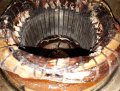
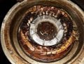
After taking it apart I noticed there was dried glue or enamel between the windings and on the top of the gearbox. Part of the centrifugal switch has molten but after reinstalling it in the motor it's seems to be working normal.
Windings:


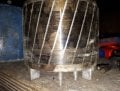
Gearbox:

Centrifugal switch:


After knowing how the motor works and rewiring it, it still keeps tripping the breaker when testing it. Does anyone have any idea what might be going on and how to fix this?
After rewiring:


So I've got this rotary floor sander I've got to fix. When I opened it I noticed someone had fixed it before and 1 of the capacitors had swollen. I've been told it had been working for a long time before the capacitor broke. I assumed the silver one was the run capacitor and the blue broken one was the starting capacitor so I ordered one with the same capacitance (big white one), which apparently is way bigger than the original.
Motor:
Capacitors:
When I hooked it up the motor just buzzed for a second before tripping the breaker. Not knowing what was going on and not being sure how the motor was supposed to be wired, I took it apart. It has 5 wires, and as expected, the 3 thicker colored ones are the 2 windings, which measured about 1 and 2.9? ohm. I was pretty sure the other 2 wires were the centrifugal switch, but doing a continuity test while turning the motor gave mixed results.
After taking it apart I noticed there was dried glue or enamel between the windings and on the top of the gearbox. Part of the centrifugal switch has molten but after reinstalling it in the motor it's seems to be working normal.
Windings:
Gearbox:
Centrifugal switch:
After knowing how the motor works and rewiring it, it still keeps tripping the breaker when testing it. Does anyone have any idea what might be going on and how to fix this?
After rewiring:
Attachments
-
 227.3 KB Views: 11
") That would be a very good motor type guy. </EDIT>
That would be a very good motor type guy. </EDIT>