Single Phase Double Capacitation Induction Motor, YL90L-4, 33686 Central Machinery Column Mill

Thread Starter

VantaSteel

Joined Aug 8, 2024
5
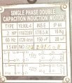
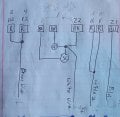
Recently bought this mill, drum switch wasn't wired up, so I wired it up, as directed in manual for 110v. Turns on and rotates forward, and reverse, but not under any load.

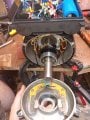
Replaced starting capacitor, and checked, and re-soldered centrifugal switch. Isolated and measured resistance across motor leads. 5.5 across pair of reds, 5.5 across second set of reds, and 10.5 across blue leads. Black wires are either pole of centrifugal switch, and switch can be heard when motor reaches speed, and has continuity when measured.

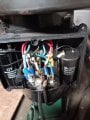
I also checked resistance in the cord, to the control wires. In the FWD position, the white wire and (2)blue wire are energized. In the REV position, the white wire and brown wire are energized.

The ceramic terminal is broken, so I'm not sure if it was re-wired correctly. Anyone have any ideas why the starting capacitor circuit doesn't seem to be working?
 

Attachments

Thread Starter

VantaSteel

Joined Aug 8, 2024
5
Also, peoples first question will probably be about the wiring diagram, which is the same as the others i've seen for this. Regardless, this is what's on the motor plate. The reason the capacitor is blue and black, is because I replaced it thinking that might be where the error is.
 

Attachments

MaxHeadRoom

Joined Jul 18, 2013
30,557
Where the heck is this motor made ? "Capacition Induction Motor"
Ensure the centrifugal start SW is opening.
Check current when running.
 

Thread Starter

VantaSteel

Joined Aug 8, 2024
5
This is the same Chinese motor you helped someone else troubleshoot. I can hear the centrifugal switch activate when it turns on. N The circuit has continuity before it reaches speed. Can you explain how that would help troubleshoot it?
I don't have any tools to check current. Would I check the general current? And what tool would I need for that?
Also, this motor has a plate that says it was professionally refurbished.
 

MaxHeadRoom

Joined Jul 18, 2013
30,557
For current, a clamp on ammeter is generally used. it would be interesting to know if the operating current was higher or lower than expected.
 
Last edited:

Thread Starter

VantaSteel

Joined Aug 8, 2024
5
Ammeter measured brown wire to two red wire windings(5.5 ohm resistance) Measures 16 amps. I measured the Blue "always" energized wire, and it was low around 2 amps.

I also managed to pop the breaker once, on start.

I looked at the wiring diagram, and the control wires all look like they are wired correctly according to the diagram 110v FWD, and Reverse situation.

However, the two capacitors would have originally been wired to the ceramic terminal.
Like I mentioned, the ceramic terminal broke so I'm not convinced its wired correctly. The starting capacitor, its not in line with the running capacitor. It looks to me, like the blue windings would have power going through them, and the running capacitor. Shouldn't the centrifugal switch be in series with that winding?
 

MaxHeadRoom

Joined Jul 18, 2013
30,557
The usual way is the start cap and run cap are both in parallel with each other, these are then in series with the start winding with the start cap being the larger value,
The start cap however has the centrifugal SW in series.
Once up to speed, the centrifugal SW opens and the start cap is disconnected. Just leaving the smaller run cap in circuit with the start winding.
If the windings have two different values, the higher resistance one being the start winding.

1725558555057.png
 
Last edited:

Thread Starter

VantaSteel

Joined Aug 8, 2024
5
After hours and hours, of research, I finally am starting to understand. I was confused when I first started this, but the starting capacitor, and running capacitor as you show are in parallel! It was wired incorrectly, as I thought, because the Starting capacitor was isolated, I simply made it parallel with the centrifugal switch between the load wire and the capacitor.

Bonus files, i've seen a few people ask about the DRUM SWITCH, now that I know mine is correctly wired up, here are two pictures of slightly different angles that shows the wiring and jumpers!

Thank you MaxHeadRoom, that last diagram really helped!20240903_180238.jpg20240903_180253.jpg
 
Top