 Facebook
 Google
 GitHub
 Linkedin
Problem Statement: Issues with single phase AC Chopper Circuit (230V / 50Hz)
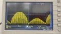
100Ω load: The chopped AC waveform appears on both cycles, but the positive half-cycle chopping is still improper (Figure 4)
I suspect the issue might be related to insufficient MOSFET turn-off time during the positive cycle.
Components Tested (Output remains unchanged):
1. Diode Bridge:
3. Gate Drivers:
Request for Help:
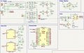
- I am working on designing a single-phase AC Chopper circuit to chop a 230V @ 50Hz AC signal. For testing and safety, I am currently using 25V AC from a variac with only one MOSFET in use (auxiliary circuitry disconnected). The circuit is being tested on a zero PCB.
- I have attached the circuit diagram and oscilloscope waveforms (observations) for reference.
- Even if after trying with better components the output remains the same, just some slight improvement.
- Figures uploaded:
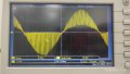
- Figure 1: Waveform observed when Input is 230V AC and output is measures across a voltage divider.
- Figures 2, 3, 4, 5.1 & 5.2 are tested with 25V AC input
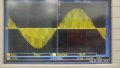
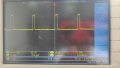
- Figure 2: Waveform across Collector-Emitter
- Figure 3: Waveform across final output with resistive load (5K resistor)
- Figure 4: Waveform across final output with resistive load (100-ohm resistor)
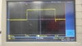
- Figure 5.1: Gate waveform (zoomed in )
- Figure 5.2: Gate waveform (zoomed out)
- Figure 6: Circuit diagram.
- With a resistive load connected:
100Ω load: The chopped AC waveform appears on both cycles, but the positive half-cycle chopping is still improper (Figure 4)
I suspect the issue might be related to insufficient MOSFET turn-off time during the positive cycle.
Components Tested (Output remains unchanged):
1. Diode Bridge:
- MUR460 with RC snubber (R = 10Ω, C = 1nF)
- S20C70CE Schottky diode
- H20R1203 IGBT
- IRFP460 MOSFET
- IRFP350 MOSFET
- STW48N60M2 MOSFET
3. Gate Drivers:
- IR2110 (2.5A)
- TC4420 (4A)
- IXDN602PI (2A)
- UCC27322 (9A)
(Tried higher current drivers, but no improvement in switching behaviour.)
- MUR460 + 10Ω resistor
- S20C70CE + 10Ω resistor
- PWM frequency: 4.4 kHz @ 10% duty cycle
- Future goal: make duty cycle variable
- Why does the positive half-cycle not chop properly, while the negative cycle does?
- Could this be due to MOSFET turn-off delay, snubber design, or something in the gate drive timing?
- Are there design changes or driver configurations that could ensure symmetrical chopping across both half-cycles?
Attachments
-
 88.4 KB Views: 23
 -
 92.2 KB Views: 23
 -
 88 KB Views: 21
 -
 71.2 KB Views: 25
 -
 105 KB Views: 30
 -
 168.2 KB Views: 32
 -
 88.2 KB Views: 31


