Problems reversing a field-wound motor driven by an electronic speed controller...

Alec_t

Joined Sep 17, 2013
15,120
it looked to me as if the max current was 60mA
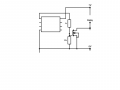
There's a wide manufacturing tolerance, and you need to design for a worst case scenario.
Something like a TIP120 would switch the relay coil, but it seems to require 60v?
That's the maximum it will tolerate without breaking down. Lower applied voltage is fine.
I was hoping that the same circuit would do for boats running on 6V to 12V - different relay coils, obviously.
Yes, the circuit (with the right relay) would suit 6V or 12V.
 

Alec_t

Joined Sep 17, 2013
15,120
It should do nicely. It has a current gain (hfe) of around 1000 at collector currents the relay coil is likely to need. If the coil needed, say, 500mA (unlikely that much) the minimum base current would be only ~0.5mA, and even ten times that would be well within the comparator's drive capability. We're only guessing at relay coil current. The datasheet of a prospective relay should be checked.
Bear in mind that if relay coil current were 500mA the TIP120 would be wasting about 2V x 500mA = 1Watt and would get hot without a heatsink.
 

Thread Starter

Dodgy Geezer

Joined Nov 30, 2009
181
.............
Bear in mind that if relay coil current were 500mA the TIP120 would be wasting about 2V x 500mA = 1Watt and would get hot without a heatsink.
I suppose that would be the case with any item passing that power. Luckily, energising only on reverse is likely to mean short-term intermittent use...
 

Alec_t

Joined Sep 17, 2013
15,120
That's where a MOSFET has the advantage. The voltage drop at 1A drain current could be as low as ~20mV, so the power wastage would then be only 20mW.
 

Thread Starter

Dodgy Geezer

Joined Nov 30, 2009
181
That's where a MOSFET has the advantage. The voltage drop at 1A drain current could be as low as ~20mV, so the power wastage would then be only 20mW.
But is there a MOSFET which can be driven by the comparator running with a 6v power supply - perhaps outputting 4v for switching from a flattening battery - and also take 12V from a newly charged 12V battery?
 

Alec_t

Joined Sep 17, 2013
15,120
Yes. Go to the web-site of any major distributor (e.g. Digikey, Elment14, ...) and use their parametric search function to see a selection of N-channel MOSFETS with a Vgs(thr) rating of less than about 2.5V.
 

Alec_t

Joined Sep 17, 2013
15,120
I suggest you do a bit of searching for DPDT relays with a coil voltage <12V, able to switch at least 5A of DC current, I couldn't find any in a brief search :(.
 

Thread Starter

Dodgy Geezer

Joined Nov 30, 2009
181
Looking up components on a manufacturers site? Wow - that's a professional step-up for me! A 2n7000 seems to fit the bill. Incidentally, a batch of LM393 comparators just came in, and I put together your circuit for the LM339 using one - but using twin sensor wires rather than the potential divider. Twin wires mean one less 33k resistor, and if the relay is mounted on the pcb and the detection is taken from the coil then two wires isn't an issue.

When I ran it, it worked, with an odd glitch. As usual I used a detector LED - this stayed out on the 'forward' cycle, and promptly came on when I dropped to 0v. Then it went out, and came back on again at about -0.5V - and stayed on throughout the reverse cycle. That's with the 330k hysteresis resistor. I wonder why this was? It happens both ways - when dropping from forward to reverse and when passing up from reverse to forward. I don't think it's a capacitor emptying - if I hold the voltage carefully at 0V then I can keep the LED on - though it flickers a lot.

By the way, what simulator do you use? They sound very useful rather than continually burning my fingers with small modern components. It was never like this with valve holders... :)
 

Thread Starter

Dodgy Geezer

Joined Nov 30, 2009
181
I suggest you do a bit of searching for DPDT relays with a coil voltage <12V, able to switch at least 5A of DC current, I couldn't find any in a brief search :(.
I found some cheap Chinese ones - with no coil specs - and of course Chinese amps are much smaller than Western amps :) I have one coming - only then will I know the coil size...

It's very kind of you to help in this way. Under your patient guidance we seem to have got the problem sorted - at least until the relay comes and I start to assemble the whole thing. I suspect that will be after Christmas now. You have scored over 1000 views, so many people will have gained from this exercise!
 

Thread Starter

Dodgy Geezer

Joined Nov 30, 2009
181
I suggest you do a bit of searching for DPDT relays with a coil voltage <12V, able to switch at least 5A of DC current, I couldn't find any in a brief search :(.
I should be the one doing the searching - there is no point you wasting time on mundane issues! This is one I have bought - https://www.ebay.co.uk/itm/5-6-12-2...var=484854156904&_trksid=p2057872.m2749.l2649

The high amperage will only be carry current, not switching, so the relay can probably be uprated. I note that this one has a 450mA coil, close to my uneducated guess of 0.5A! They recommend a single unit Darlington pair MPSA13 for switching. I calculated that to mean a feed resistor of about 15 ohms, and a power dissipation of about 3.5W - which seemed excessive - but they suggest a value of 1k, which sounds a lot better....
 

Alec_t

Joined Sep 17, 2013
15,120
By the way, what simulator do you use?
LTspice. A free download from Analog Devices. Many members of this forum use it. There's a Yahoo LTspice user group which can offer loads of free third party sim models as well as help. Loads of tutorials available too. The download includes example sims and help. The learning curve is well worth climbing.
I suspect your motor noise is getting through somewhere and upsetting the LED. Hopefully the inertia and inductance of the relay will avoid chatter.
They recommend a single unit Darlington pair MPSA13 for switching.
Don't think that would last long! According to its datasheet, at only 100mA collector current its saturation voltage is 1.5V. In practice that voltage will be higher at 450mA current. Even optimistically though, 1.5V x 450mA = 675mW power wasted. But the rated power is only 625mW! Don't think much of their recommendation :rolleyes:.
Not sure how you calculated your feed resistor value or power dissipation. Base current should be less than 1mA for a Darlington, given its current gain of >1000. Even if we assumed each component transistor in the Darlington needed 1/10 its collector current as base drive, that would be a notional current gain of 10 x 10 =100 and notional input base current of 450mA/100 = 4.5mA.
 

Thread Starter

Dodgy Geezer

Joined Nov 30, 2009
181
..........
Don't think that would last long! According to its datasheet, at only 100mA collector current its saturation voltage is 1.5V. In practice that voltage will be higher at 450mA current. Even optimistically though, 1.5V x 450mA = 675mW power wasted. But the rated power is only 625mW! Don't think much of their recommendation :rolleyes:.
hmm... that transistor was taken from their example documentation. I've obviously misread what it was referring to. Perhaps I'd better stay with the 2N7000.


Not sure how you calculated your feed resistor value or power dissipation. Base current should be less than 1mA for a Darlington, given its current gain of >1000. Even if we assumed each component transistor in the Darlington needed 1/10 its collector current as base drive, that would be a notional current gain of 10 x 10 =100 and notional input base current of 450mA/100 = 4.5mA.
Obviously incorrectly :( I tried to use a MOSFET gate resistor calculator for the 2N7000, but it asked for values which did not seem to be mentioned on the datasheet. It looked as if you need 2v on the gate to turn it on, so around 500 ohm to 1k should work? Most of the theory documentation on MOSFETS mentions frequency, which does not seem to apply here....
 

Alec_t

Joined Sep 17, 2013
15,120
MOSFETS are voltage-driven, not current-driven. Gate current is virtually zero except during the brief instant of turn on or turn off when the gate capacitance is being charged or discharged. A few tens of Ohms are usually included in the gate drive path, simply to limit that current (and also damp any spurious high frequency oscillations).
2V will begin to turn a 2N7000 on if you're lucky, since its Vgs(thr) (the voltage needed for only 1mA drain current) can be anywhere between 0.8 and 3V, per the datasheet. However, the 2N7000 is unsuitable here as its maximum allowable drain current is only 200mA.
 

Thread Starter

Dodgy Geezer

Joined Nov 30, 2009
181
Well, I've spent much of the evening trying to make the product selection pages work - they don't seem to like the Opera browser :(

I've come up with an IRFZ34, or perhaps an IRF510 /20/30/40. I cheated by going to ebay, seeing the commonest components bought, then looking at the datasheets for one that would handle about an amp, and needed 2-4 V to let it run. I should be able to guarantee 3V from the comparator - 50ohms will do that....
 
Last edited:

shortbus

Joined Sep 30, 2009
10,049
I've come up with an IRFZ34, or perhaps an IRF510 /20/30/40. I cheated by going to ebay, seeing the commonest components bought, then looking at the datasheets for one that would handle about an amp, and needed 2-4 V to let it run. I should be able to guarantee 3V from the comparator
I may be missing something here but if you only have 3V for the gate, the mosfets you chose aren't ones I would use. 3V is only a little above the "threshold" voltage of the gate on those mofsets, not a good way to run a mosfet. The threshold is where it is just barely turned on and is usually used to figure out where a mosfet is off, not on. Using the gate threshold will cause the mosfet to run hot. You should look for something called a "logic level mosfet'. But maybe Alec will tell me if I'm right or wrong about this.
 

Thread Starter

Dodgy Geezer

Joined Nov 30, 2009
181
Ah, I recall some mention of logic-level earlier... I should have between 5 - 12V from the comparator, depending on the battery used and the state of charge, and the data sheets said that the gate voltage was 2-4V, which I took to be the range, thus assuming 3V would be fine. Would I be better off with no gate resistor at all? Or would this be a good way to connect the MOSFET?
 

Attachments

Last edited:

Alec_t

Joined Sep 17, 2013
15,120
If the comparator is a LM339/393 then it will need a pull-up resistor of, say, 10k. The gate resistor (may not be needed) from the comparator could be 10-47 Ohms (not critical) and the pull-down resistor can be, say, 33k (also not critical and maybe unnecessary).
Re the MOSFET, would you be looking for a surface mount type or a through-hole type? Here's a bunch of logic-level ones with a rated Vgs(th) of 2V @ 1mA.
 

Thread Starter

Dodgy Geezer

Joined Nov 30, 2009
181
I am looking for through-hole components - but do I have to have a logic-level component if I can achieve a gate voltage of 5V? The ones you have listed are all quite expensive, over 10 times the cost of an IRF520, and it looks as if that can be turned on with 2V to 4V.
 

Alec_t

Joined Sep 17, 2013
15,120
but do I have to have a logic-level component if I can achieve a gate voltage of 5V?
A logic-level one will turn on (almost) fully at 5V, but a non-logic-level one will only give a trickle of current at 5V and needs about 10V to turn on fully. For example, the IRF520 datasheet says Vgs(th) may be as low as 2V but could be as high as 4V (there is a wide manufacturing tolerance) and the drain current then would be only 250 microAmps!
The IRL540 is a reasonably-priced logic-level type.
 
Top