Problems reversing a field-wound motor driven by an electronic speed controller...

Thread Starter

Dodgy Geezer

Joined Nov 30, 2009
181
The transistor pin-out is important :). How/where is the LED connected?
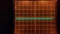
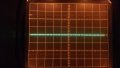
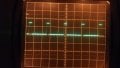
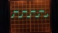
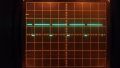
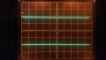
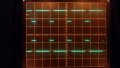
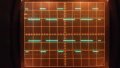
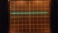
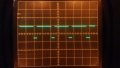
A pic of your actual build may help, also the motor spec. 'Scope shots (scope DC coupled) of the waveforms at both ESC output terminals, with the motor connected, would be useful.
What ESC are you driving the circuit with? Do the power supply, ESC and built circuit have their grounds commoned?

Edit: Re the RFI, I'm no expert but perhaps the split field winding and coil shape/positioning allowed partial cancellation of parasitic external magnetic fields.
Pinouts are important - if I were an electronics expert I would probably not forget them in the few seconds between looking them up and soldering them!!

1 - the led is soldered to a dropping resistor, and placed across where the relay coils would go. between +tve and the collector of the transistor, which in this case is a D467C.

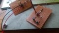
2 - pics of builds included. I am using a 37ohm and a 10ohm to make up the 47ohm. The back shows signs of multiple resoldering!

3 - the ESC is a common cheapo Chinese one - often called a bluefin after its heatsink colour. I can't remember the specs, but it's reversible. You can have a picture if you like. I would expect to trial the circuits with multiple ESCs before putting them out on a website. Power is from 7.4v Lipo and negative is connected to ESC, base of circuit and frame of scope. Motor frame is not earthed.

4 - . Pics included of probe at one motor terminal. This is positive-going when the motor goes forward, and the circuit should not turn on under that situation. Pic 1 shows the motor at full on, Pic 2 half, pic 3 just on. At pic 1 the Led is not lit but flickering, at Pics 2 and 3 it is on.
 

Attachments

Thread Starter

Dodgy Geezer

Joined Nov 30, 2009
181
It seems to me that both terminals pulse a bit during the half-way process. The one which is going to go high eventually does so with a flat high voltage, while the one which is going to stay low eventually does so with a flat low voltage. This results in the LED being on continually in one direction, also going on in the other direction, but turning off when that direction reaches max power/low voltage.

Incidentally, the motor I was using was the Taycol Marine. The only specs that are available are on these pages - http://taycol.tk/Documents.html
The Marine is not covered by any of the documents, but it is very similar to the Supermarine. These two pages are about all you will get...
http://taycol.tk/Tayins602.jpg
http://taycol.tk/tayins603.jpg
 

Alec_t

Joined Sep 17, 2013
15,120
I'm confused by your 'scope shots. What do 0% and 100% represent? Where is the ground reference? What horizontal scale was used (I assume 5V per division vertical)? Why is dia5 titled 'just on neg full on'?
It seems to me that both terminals pulse a bit during the half-way process.
Ahh, that's could be due to electronic braking of the motor during the reversal, done by intermittently connecting both terminals simultaneously to ground (or to the +ve rail). It makes sense but it complicates things. If such braking is applied then my simple circuit won't suffice. I don't think a simple comparator circuit would either :(.
 

Thread Starter

Dodgy Geezer

Joined Nov 30, 2009
181
I'm confused by your 'scope shots. What do 0% and 100% represent? Where is the ground reference? What horizontal scale was used (I assume 5V per division vertical)? Why is dia5 titled 'just on neg full on'?

Ahh, that's could be due to electronic braking of the motor during the reversal, done by intermittently connecting both terminals simultaneously to ground (or to the +ve rail). It makes sense but it complicates things. If such braking is applied then my simple circuit won't suffice. I don't think a simple comparator circuit would either :(.

Ah. I thought that the ideas of 'forward and 'backward' would get confusing. They confused me when I was trying to do the data gathering.

First, we have the radio transmitter. This used to transmit pulses to the receiver but nowadays on 2.4Ghz it probably transmits a data frame, and that can be set to be forwards or backwards by software in the transmitter. The receiver then sends pulses to the ESC - between 1 and 2ms long, and the ESC converts these into PWM - either between 0% to 100% piwer, or 100% to 0% to -100% in the case of a reversible ESC. It might do 100% to 0% to -50% if it only allows a half speed in reverse, and it might spread the 100% to 0% over more than half the allocated band. Then we have the polarity of the motor, which will usually reverse forwards and backwards again - although not for a field-wound...

My head was spinning as I tried to sort out which way the pulses ought to be going......

The ESC will not work unless there is a motor attached.Further, you have to drop the stick to full reverse and back to centre again to arm the ESC. I shall produce a new set of pictures with no circuit connected, and just take a reading off one terminal The other terminal ought to be matching the opposite...

1 R/C stick central - ESC armed - no movement of motor
2 stick slightly forwards - motor just turning
3 stick 3/4 forwards - motor running well
4 stick full forwards - motor full

5 stick slightly back - motor just turning
6 stick 3/4 back - motor running
7 stick full back - motor on full


I can see that this one terminal is locked to 0v when fast forward, and +7v when fast reverse. But in the middle it seems to pulse.... It would be interesting to know whether any of this makes sense to you...
 

Attachments

Last edited:

Thread Starter

Dodgy Geezer

Joined Nov 30, 2009
181
Interestingly, the polarity detector circuit is running ok. That works by first converting the PWM at a single terminal to DC, using a 33k resistor and a 0.01uf capacitor. Then feeding that into the inverting input (whatever that means) of an LM358 while holding the non-inverting input to ground. That seems to give a good detection on positive - though I do get a few glitches if I swing the control stick rapidly up an down. It would be nice to suppress those if only I knew what was happening...
 
Last edited:

Thread Starter

Dodgy Geezer

Joined Nov 30, 2009
181
What do 0% and 100% represent? Where is the ground reference? What horizontal scale was used (I assume 5V per division vertical)? Why is dia5 titled 'just on neg full on'?

I'm not a specialist in electronics, and am poor on scope work. You are right that it is 5V/cm. The diagrams were titled to remind me what they were about - I didn't think anyone else would be looking at the titles! In that case it stood for 'Diagnostic shot 5 - negative stick just on a little - LED fully lit....

I don't think the ESC does electronic braking. The polarity detector seems to work.
 

Alec_t

Joined Sep 17, 2013
15,120
1 R/C stick central - ESC armed - no movement of motor
But in the middle it seems to pulse
Those two conditions seem inconsistent. Where is zero volts on the scope traces? Was the scope probe DC-coupled?
The other terminal ought to be matching the opposite...
But does it? It would be helpful if you had a dual-channel scope so that the waveforms at both motor terminals could be observed simultaneously.
What is the time per division of the scope shots? This info would tell us the pulse frequency and help with fine tuning R and C values for any circuit.
 

Thread Starter

Dodgy Geezer

Joined Nov 30, 2009
181
Those two conditions seem inconsistent. Where is zero volts on the scope traces? Was the scope probe DC-coupled?

But does it? It would be helpful if you had a dual-channel scope so that the waveforms at both motor terminals could be observed simultaneously.
What is the time per division of the scope shots? This info would tell us the pulse frequency and help with fine tuning R and C values for any circuit.
Zero was central in the scope. 5V/cm, and 0.2ms/cm (I think!). The traces have DC Coupled set (whatever that means...). I meant that at zero there is no voltage or pulsing (obviously), while when you move the stick to a positive or negative position there is pulsing. I knew we would have confusion. The stick controls the ESC in a "-100% to 0 to +100%" manner - so from one point of view 'the middle' is zero, whereas 'middle power' is about 25% or 75% stick movement....

Dual-channel scope? Which mediaeval philosophy specialist does not have a dual-channel scope? Or a wind-tunnel....? Essential items when studying Thomistic hylomorphism or Bacon's Opus Tertium.... See, for instance, the statistician William Briggs http://wmbriggs.com/post/20377/ :)

Here are scope shots of both terminals - the zero line is as the initial shot. Forwards and backwards refers to the R/C control stick. Start is stick centred with no movement, then the stick is moved forwards and backwards. Of course, these are nominal directions and can easily be reversed at the transmitter.... :
 

Attachments

Thread Starter

Dodgy Geezer

Joined Nov 30, 2009
181
I see that terminal A switches on for, say, 75% of the time while terminal B is at ground. And then for the remaining 25%, terminal A drops to ground and terminal B goes high. Do you think this is because the motor is turning and generating? If so, I'd expect to see some ripple in the 'terminal B high' line... which you see in these shots of a slow run. Note with the expanded view the 'on' seems flat, but the rest seems to ripple. Not sure if this an artefact or not, of course....
 

Attachments

Alec_t

Joined Sep 17, 2013
15,120
Ok. From the latter pics it's clear that the ESC has a ~2.5kHz PWM pulse rate and treats a 50% duty cycle as 'neutral', with 0% and 100% duty cycles corresponding to full forward and full reverse. Ripple on the waveforms is to be expected, due inter alia to commutation effects. It's apparent that a 'true' waveform is applied to one terminal A and the inverse of that is applied to the other terminal B. Neither terminal is clamped to a rail as I hypothesised originally. Simulation shows that with this arrangement for driving A and B the comparator circuit, when tweaked, should work to distinguish forward from reverse. The comparator needs to switch at the 50% duty cycle point.
 

Thread Starter

Dodgy Geezer

Joined Nov 30, 2009
181
Ah well, it was worth trying, and taught me many things. Thank you for that!

What do you mean by 'tweaking' the comparator circuit? Are the values of 33k and 0.01uf optimum for the input, with the other held at ground? Do I need a diode in front of them? It would be interesting to see a simulation of the comparator circuit. ...
I have a couple of other Chinese ESCs on order, so when they turn up I can see if they behave the same way....
 

Alec_t

Joined Sep 17, 2013
15,120
Are the values of 33k and 0.01uf optimum for the input, with the other held at ground?
No. According to my sim you would need fatter caps (100n at least) for smoothing the comparator inputs and at least 10uF from the relay-switching transistor collector to ground to minimise switching glitches if the PWM frequency is only a couple of kHz; also, the 'other ' would need to be at half the supply voltage instead of ground to achieve switching at the 50% duty cycle point.
Here's the sim :-
ESC-reverser5.PNG
The ramped waveform at the inverting input of the '358 arises as the PWM duty cycle goes from 98% down to 2% then back up again. R4 provides positive feedback to reduce jitter. D1-4 are belt and braces voltage spike suppressors, though it looks from your scope shots that these are being effectively suppressed by the ESC.
My motor model has a back-EMF output (referenced to the B terminal) indicative of rotor speed, and has an Lt input representing load torque. I have assumed the torque is proportional to propeller rpm.
 
Last edited:

Thread Starter

Dodgy Geezer

Joined Nov 30, 2009
181
Er...Wow!

I thought that the circuit I had was switching reliably. There's a lot there that I don't understand...

First, I don't understand what the 4 diodes are doing at the ESG input. Are they removing motor back emf?
Then there's the 'other' - the 'non-inverting input'. That is just connected to ground in my circuit - because I want the comparator to switch when one terminal is, on average, positive with respect to the other.

It is conceivable that an ESC may not switch polarity at the 50% point. Vehicles usually do not require as much speed in reverse as forwards, and I can imagine control circuits presenting an 'off-centred' neutral, giving 100- 0% voltage in 3/4 of the stick movement, and perhaps negative 0-50% voltage in the remaining 1/4 of stick movement. I saw detection of polarity change at the motor as having the advantage that this issue would not be a problem. To enable this I assumed that the non-inverting input had to be at ground - 0V.

The design philosophy was simple. Hold one line low, then smooth the PWM signal with a resistor/capacitor pair so that it becomes a DC signal. Then compare them and when the DC signal goes +ve, switch the coil.

Your non-inverting input is held at mid voltage by a resistor pair, but then it's connected to ground via a capacitor, and connected to the signal output via a resistor. I can't understand what thee are doing.

I'll put the circuit together and see what it does! It may take me a bit of time, as I have other work to do as well....
 

shortbus

Joined Sep 30, 2009
10,049
Vehicles usually do not require as much speed in reverse as forwards,
This is true in cars and trucks but due to transmission gearing.

Would using a 339/393 instead of the 358 be better for the comparator part of the circuit? Since the 339/393 is a real comparator and not an opamp like the 358 that is being used as a comparator.
 

Thread Starter

Dodgy Geezer

Joined Nov 30, 2009
181
This is true in cars and trucks but due to transmission gearing.

Would using a 339/393 instead of the 358 be better for the comparator part of the circuit? Since the 339/393 is a real comparator and not an opamp like the 358 that is being used as a comparator.


It's true in trucks, cars, boats and most vehicles. Because they are usually optimised to go one direction, and therefore going in reverse usually causes control problems - you have to do it slowly. In boats, for instance, the stern will dig into the water. In cars, steering is trickier. Only in trains is it reasonable to go as fast backwards as forwards. Models simply match their full-size counterparts....


I did not know about a 393. Looks like a redesign is called for...is the 8 pin DIP package basically the same pinout as an LM358?
 
Last edited:

Alec_t

Joined Sep 17, 2013
15,120
It is conceivable that an ESC may not switch polarity at the 50% point.
Indeed; but the one you used to get the 'scope shots clearly does :D. In the post #54 circuit you could replace R2 and R3 with a 50k potentiometer, with the wiper going to the non-inverting input of the comparator, to allow adjustment of the trip point as required.
but then it's connected to ground via a capacitor
That's to decouple any transients on the +ve supply rail, i.e to smoothe/stabilise the '358 input voltage.
The design philosophy was simple. Hold one line low, then smooth the PWM signal with a resistor/capacitor pair so that it becomes a DC signal. Then compare them and when the DC signal goes +ve, switch the coil.
Unfortunately that doesn't work reliably when the A and B inputs are both pulsed alternately high and low by the ESC. Here's the sim result :-
ReverserFail.PNG
You can see that the smoothed voltage Vinv never goes below the non-inverting input voltage (ground).
 

Thread Starter

Dodgy Geezer

Joined Nov 30, 2009
181
Indeed; but the one you used to get the 'scope shots clearly does :D. In the post #54 circuit you could replace R2 and R3 with a 50k potentiometer, with the wiper going to the non-inverting input of the comparator, to allow adjustment of the trip point as required.

That's to decouple any transients on the +ve supply rail, i.e to smoothe/stabilise the '358 input voltage.

Unfortunately that doesn't work reliably when the A and B inputs are both pulsed alternately high and low by the ESC. Here's the sim result :-
View attachment 165311
You can see that the smoothed voltage Vinv never goes below the non-inverting input voltage (ground).
I am going to try two or three different ESCs - the idea was that the circuit should be of general use, rather than specific to thisapplication. it's intended for other vintage modellers using these motors...

If the smoothing system won't work, i wonder why it's working on my simple circuit at the moment. I compare an arbitrary motor terminal to battery negative, and that seems to work. It used to fail by switching off when I held full reverse on, but the small cap cleared that. i will will see if it's better with a potential divider and a larger smoothing cap.
 

Thread Starter

Dodgy Geezer

Joined Nov 30, 2009
181
hmm... just putting the 2 3.3k resistors in makes the indicator led stay on at all times except full reverse... and the idea of adjusting the trip point with a pot rather misses the concept of the circuit. We want to detect when the motor is energised in a 'backwards' direction - that is, when polarity changes. That is when the relay needs to switch the coil around. Switching the coil at any other time would not meet the requirement, and could be dangerous...

As an aside, the relay will not switch the ESC output. The ESC output goes to the motor input unswitched, and not as part of this circuit. The relay provides crossover switching to reverse the field coil (or armature) - again, outside this circuit. The aim of the circuit is simply to determine when the ESC polarity changes, and energise a relay on one polarity condition which will be designated 'reverse'....
 
Last edited:
Top