PNP and NPN recommendation for mosfet driver

Thread Starter

MrsssSu

Joined Sep 28, 2021
267
Don't do that - current will flow through the base-collector diode of Q1, and you will need a new Q1.
Hi, yes you are right. Q1 is the hottest. So, what should I do to feed the gate of mosfet with 16V square wave if V1 is not allowed at 16V because the voltage fed into gate of mosfet is determined by the magnitude of V1? Thank you :)
 

Ian0

Joined Aug 7, 2020
13,207
Hi, yes you are right. Q1 is the hottest. So, what should I do to feed the gate of mosfet with 16V square wave if V1 is not allowed at 16V because the voltage fed into gate of mosfet is determined by the magnitude of V1? Thank you :)
You can't drive 16V into the MOSFET unless your power supply (V2) is >16V
Why do you want to drive 16V into the MOSFET? It is unlikely to work any better than if you use 12V.
 

Thread Starter

MrsssSu

Joined Sep 28, 2021
267
You can't drive 16V into the MOSFET unless your power supply (V2) is >16V
Why do you want to drive 16V into the MOSFET? It is unlikely to work any better than if you use 12V.
Yes, I know. I am just curious, if V2 is 20V and V1 is 16V square wave, the transistors should be working fine right? So, are you saying that V2 must always be greater than V1 for the circuit to work effectively (transistor not hot) ? Thank you, sir
 

Ian0

Joined Aug 7, 2020
13,207
So, are you saying that V2 must always be greater than V1 for the circuit to work effectively
Yes. Absolutely.

Usually, whatever voltage supplies the circuitry that generates V1 also supplies V2.

Much more common is V1=5V and V2 = 12V or higher. In that case you need to amplify the voltage, for which I would recommend a gate driver IC.
 

Thread Starter

MrsssSu

Joined Sep 28, 2021
267
Yes. Absolutely.

Usually, whatever voltage supplies the circuitry that generates V1 also supplies V2.

Much more common is V1=5V and V2 = 12V or higher. In that case you need to amplify the voltage, for which I would recommend a gate driver IC.
Hi, if V2 is 20V and V1 is 16V square wave, the transistors should be working fine right? I am planning to test it out:)
 

Thread Starter

MrsssSu

Joined Sep 28, 2021
267
Yes.
Careful, though. Most MOSFETs don't like more than 20V on the gate.
HI, I have tested it. The problem is the transistors buzz and suddenly pop and get spoiled when I use V2 is 20V and V1 is 16V square wave. Hmm, I think I will stick with V2 (12V) and V1 (12V) . I think is because I applied a too high base voltage for the transistors, thats why it buzz and pop:). May I know what are the most common mosfet driver available in the market?
 
Last edited:

Ian0

Joined Aug 7, 2020
13,207
May I know what are the most common mosfet driver available in the market?
There are hundreds to choose from. I like MCP1401 and MCP1402. Search for "Low Side driver", there are inverting types, non-inverting types, types with additional logic functions etc.
 

crutschow

Joined Mar 14, 2008
38,627
if I set V1 at 16V square wave with a 12V (V2), transistor (Q1,Q2) get hot.
That circuit is not designed for an input voltage greater than V2.
The transistors become incorrectly biased and draw a large current.

Why do you want an input voltage greater than V2?
That serves no useful purpose.
 

Thread Starter

MrsssSu

Joined Sep 28, 2021
267
That circuit is not designed for an input voltage greater than V2.
The transistors become incorrectly biased and draw a large current.

Why do you want an input voltage greater than V2?
That serves no useful purpose.
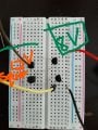
Hi sir, I attached my schematic below. Am i connecting it properly? In this case, I am using V2 lower than V1 because when I tested V2 greater than V1, the transistors becomes hot. :)Inked271828047_1221179888414519_6140697363846638897_n_LI.jpg
 

DC_Kid

Joined Feb 25, 2008
1,242
What's the goal of the ckt? What's the source (device, or output stage type) for PWM?
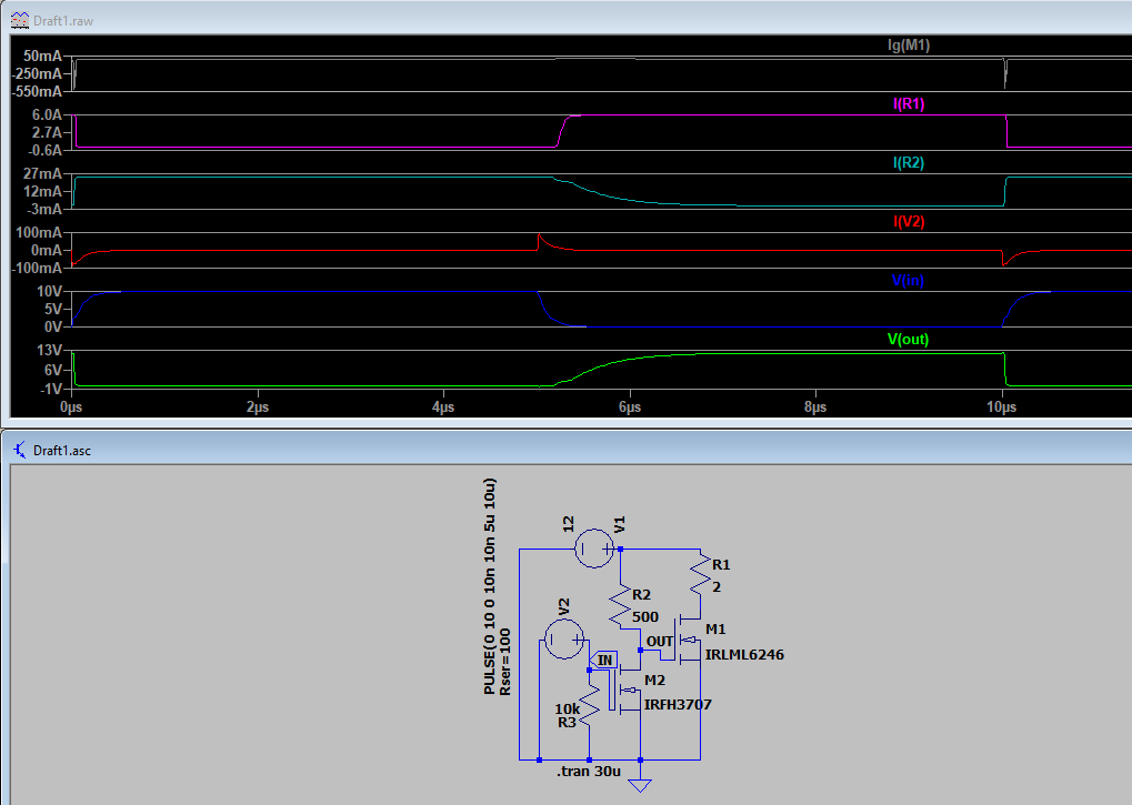
Why use bi-polar as driver, just stick a nFet in front of the power nFet. Makes the whole ckt just three parts.

The other Q I have is, does the power fet on/off need to follow PWM on/off times closely, or is some delay ok? There will always be delay, question is, how much is too much, or perhaps it doesn't matter?
 

DC_Kid

Joined Feb 25, 2008
1,242
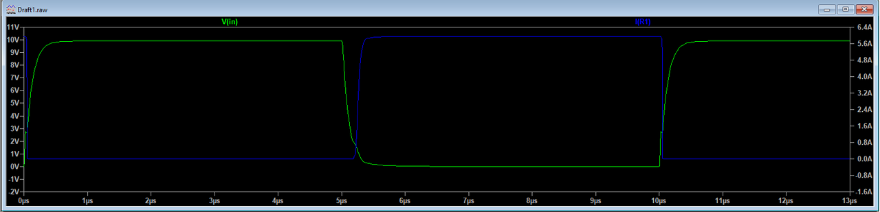
Something like this? Fast, crisp, four discrete parts, not much gate current. An interesting thing to look at, Right-clik a Voltage waveform in the simulation window, then View --> FFT. If FFT is of concern, that's a place to look.

 
Last edited:

DC_Kid

Joined Feb 25, 2008
1,242
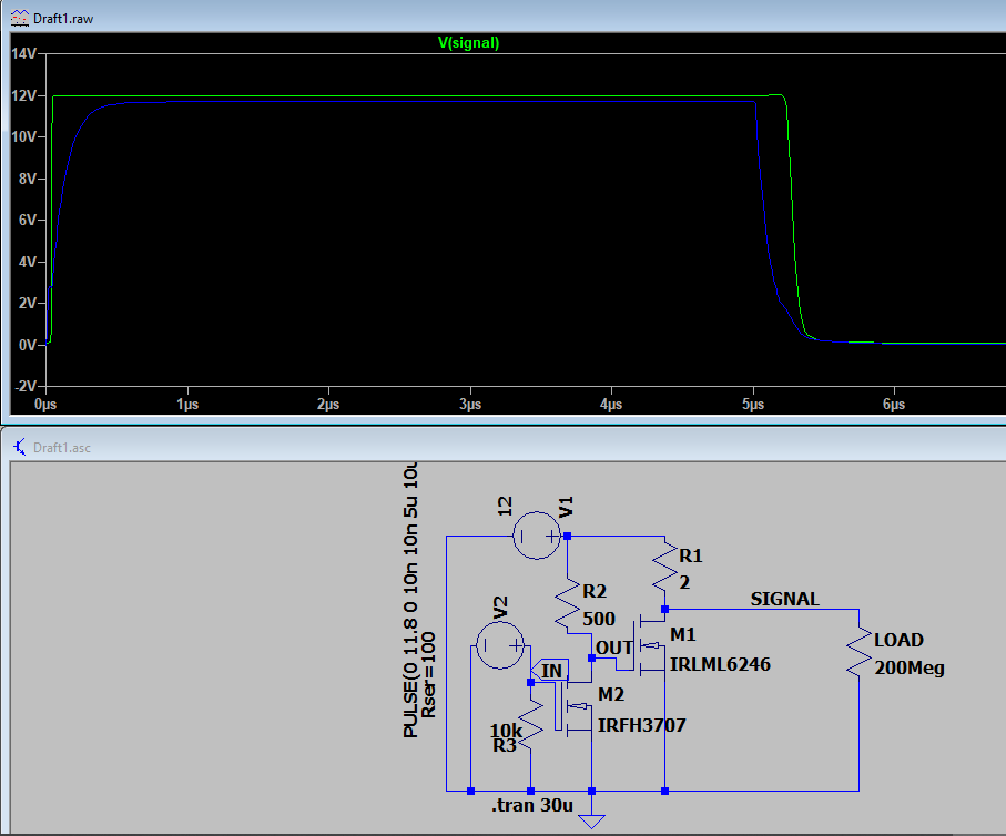
Also notice the actual power side PWM changes just a smidge. I changed Vin from 10 to 11.8 so this issue can be more easily seen in the sim window. Signal "on" time is about 1/4us longer.
 

Attachments

Top