How to build true physical intuition for circuit analysis as a beginner? (Need book recommendations)

Status
Not open for further replies.

Thread Starter

Engineering student

Joined Nov 6, 2026
3
Hi everyone,

I am a beginner university student struggling with the foundational concepts of circuit analysis.

My issue isn't with memorizing formulas, solving equations, or applying theorems like Nodal or Mesh analysis mathematically. My real problem is that I lack physical intuition. Every time I think I understand the basics, advancing to more complex topics reveals that I don't truly grasp what is happening in reality.

I want to understand the "why" and "how" behind circuits, not just the math. Specifically, I struggle with:

1. What does circuit analysis actually mean in reality? I know it means finding voltages and currents, but I struggle to visualize how voltages drop, how currents flow, and how components physically interact with each other.

2. Identifying Series vs. Parallel connections: I often get confused about relative to what we determine if components are in series or parallel, and how to track this visually across different circuit configurations.

3. The Core Rules: What are the fundamental, universal principles of circuits that would allow me to look at any circuit—even one I've never seen before—and mentally trace how it behaves?

A specific note on the resources I'm looking for:

I strongly prefer books over videos. I learn best through self-study and reading detailed written explanations. Videos often move too quickly or summarize concepts without diving deep enough into the underlying mechanics.

However, I am not looking for typical academic textbooks that rush straight into formulas, proofs, and superficial explanations of physical reality.

I am looking for books that are:

\- Deeply conceptual & intuitive: Books that spend ample text thoroughly explaining what is actually happening inside the circuit.

\- Beginner-friendly from zero to advanced: I don't mind if the book goes very deep or covers advanced topics—in fact, I welcome it! "Beginner-friendly" to me just means it starts from ground zero, assumes no prior intuitive foundation, and builds up step-by-step without skipping the conceptual "why."

If you know of any books that fit this exact description, I would be extremely grateful for your recommendations!

P.S. Also, if you have any golden advice, learning approach, or alternative solution that helped you overcome this hurdle—even if it's outside of books—please feel free to share it!

Thank you so much!
 

BobTPH

Joined Jun 5, 2013
11,677
Let’s examine why you have trouble with series and parallel circuits.

The first step in understanding circuits intuitively is understanding voltage and current intuitively. Then series and parallel are simply definitions.

So tell us what is your intuitive understanding of voltage and current?
 

dl324

Joined Mar 30, 2015
18,516
Welcome to AAC!
1. What does circuit analysis actually mean in reality? I know it means finding voltages and currents, but I struggle to visualize how voltages drop, how currents flow, and how components physically interact with each other.
I tend to look at schematics and recognize blocks based on how they're drawn. Schematics that aren't drawn conventionally take more effort to understand and I'm usually not inclined to expend the effort unless I have a real need to do so.
2. Identifying Series vs. Parallel connections: I often get confused about relative to what we determine if components are in series or parallel, and how to track this visually across different circuit configurations.
I too had difficulty recognizing series vs. parallel when I first started doing DC theory. I mentioned that to a student who was an ET in the navy. He said to just keep at it and it would become natural. It did.
3. The Core Rules: What are the fundamental, universal principles of circuits that would allow me to look at any circuit—even one I've never seen before—and mentally trace how it behaves?
Same answer as for number 1 above. Well drawn schematics are easier to comprehend than those drawn by people who don't really understand the circuit they're drawing.
I strongly prefer books over videos. I learn best through self-study and reading detailed written explanations. Videos often move too quickly or summarize concepts without diving deep enough into the underlying mechanics.
I also prefer books. When first learning, classroom lectures were invaluable. Trying to just read on your own doesn't really cut it because you don't know what you don't know. Plus a fair number of books are garbage.

I find a lot of videos on YouTube to be worthless. There's a well-known guy, from Australia or New Zealand, and I just can't stand his voice. There's another guy who is knowledgeable, but I can't stand the way he speaks (too many 'ands' and 'uhms'). Then there are the videos by many people who just don't have a clue. Any that use "schematics" that are really wiring diagrams (with actual components instead of symbols) are typically a showstopper for me.
 
Last edited:

dl324

Joined Mar 30, 2015
18,516
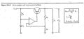
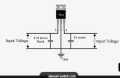
Here's a linear voltage regulator schematic from Malvino Electronic Principles (a book I don't care for):
linearRegulatorMalvino.jpg

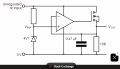
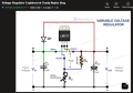
Here's a silly schematic from Stack Exchange:
1793992127179.png
I'm not a fan of offsetting connections (like Vout and the cap/resistor). The wire crossing on the inputs of the opamp wouldn't be required if they didn't show explicit power connections on the opamp and flipped its orientation.

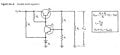
A large number of schematics on the internet use this topology. That doesn't make sense because the regulator "before" the opamp version uses a transistor feedback element like this (from Malvino):
discreteRegulatorMalvino.jpg

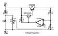
I prefer the feedback element to be drawn this way:
1793991952466.png
Excuse the gap in component designators. There was another circuit in that schematic.

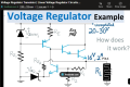
Here's an example of that awful wiring diagram schematic:
1793992859861.png
No component designators and it takes a second to notice that it doesn't use the dot connection convention because there are no other wire crossings.

Here's one that's even worse (unnecessary colors, unnecessary connection dots, and unnecessary wire jogs) :
1793993028438.png

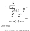
Here's how that schematic was drawn in National Semiconductor's datasheet:
1793994130393.png

Another horrible schematic:
1793994662235.png
I'm not a fan of connection dots with crossover humps. But component orientation is my biggest complaint. The pass element (Darlington) should be rotated 90 degrees CCW. R1 and D2 (Z2) should be drawn vertically. Component designators would have been nice, and the output transistor needs to be a power device. I can't fathom why they decided they needed a different symbol for the load resistor.
 
Last edited:

jjlarkin

Joined May 30, 2025
12
I'm working with kids at two nearby universities, SFSU and Cal Poly. The pattern we see is that faculty pushes equations, students learn the equations, apply them in tests, and then forget them. Few acquire real instincts for electricity. Many are outright afraid of electricity.

I have a whiteboard test that I give to EE students, a bog simple voltage divider. Most panic and say that they don't remember the equations. It's funny and sad.

We're working with one senior on a capstone project to develop a plan to give some, mostly qualitative, electrical intuition to kids in primary school, ballpark 8 or 10 years old; they can do the math later. We are designing a ruler, a little PCB, that has some LEDs and stuff on it.
 

dl324

Joined Mar 30, 2015
18,516
I'm working with kids at two nearby universities, SFSU and Cal Poly.
I wouldn't refer to them as kids. But there is a problem with primary and secondary schools in the public education system. Teachers keep advancing students that should be held back because they're underachieving, but their helicopter parents won't let the teachers do what's right. Many children have too much screen time because their parents can't be bothered to entertain/teach them. Consequently, the attention span of most of them is non-existent.
I have a whiteboard test that I give to EE students, a bog simple voltage divider. Most panic and say that they don't remember the equations. It's funny and sad.
For crying out loud - it's just a ratio.

But there are many people who use resistor color code cheat sheets and programs to calculate resistor/capacitor values for 555 timer circuits.
 

joeyd999

Joined Jun 6, 2011
6,494
My real problem is that I lack physical intuition.
This comes from actual -- physical -- doing, not analyzing equations in a book.

Get a solderless breadboard, a power supply (build your own!), and a voltmeter, and a handful of components.

Build, predict, test, and confirm your predictions.

Advance as your understanding grows.

This is how the best of us did it -- starting as kids with almost no outside input aside from the few magazines we were able to afford or procure at the library. Electronics became as natural as breathing, eventually.

Intuition is earned, not learned.
 
Last edited:

crutschow

Joined Mar 14, 2008
38,936
I want to understand the "why" and "how" behind circuits, not just the math.
I'm very much the same way.
It I don't have an intuitive understanding of something, I find it difficult to work with.

I know it's frowned on by some, but a rough analogy of electricity is to think of water in a closed-loop pipe.
A pump is the voltage source, a restriction in the pipe is a resistor, a inertia slug in the pipe is an inductance, and a flexible membrane blocking the steady flow is a capacitor.

The mechanical analogy for resistance is friction, for inductance is mass inertia, and for capacitance is a spring.
Thus the mechanical resonance/oscillation of a spring and inertia mass is similar to the electrical oscillation of an LC circuit.

For the mechanical resonance, the system energy is transferred back and forth between the momentum of the mass and the stretch of the spring.
For the electrical resonance, the system energy is transferred back and forth between the inductor current and the capacitor voltage.

Perhaps a tutorial such as this would help you.
 
Last edited:

Thread Starter

Engineering student

Joined Nov 6, 2026
3
Let’s examine why you have trouble with series and parallel circuits.

The first step in understanding circuits intuitively is understanding voltage and current intuitively. Then series and parallel are simply definitions.

So tell us what is your intuitive understanding of voltage and current?
First of all, thank you so much for taking the time to write back and help me out!
Honestly, setting academic definitions aside, whenever I try to truly picture what voltage and current are, I always default back to the water pipe analogy—where voltage is the water pressure and current is how much water passes through the pipe's cross-section per second.
I guess that's just my way of making sense of the textbook definitions: that current is the rate of charge flow through a cross-section, and voltage is the energy difference between two points that pushes electrons to move. But even knowing all of that, to be honest, it still feels pretty confusing.
 

Thread Starter

Engineering student

Joined Nov 6, 2026
3
I'm working with kids at two nearby universities, SFSU and Cal Poly. The pattern we see is that faculty pushes equations, students learn the equations, apply them in tests, and then forget them. Few acquire real instincts for electricity. Many are outright afraid of electricity.

I have a whiteboard test that I give to EE students, a bog simple voltage divider. Most panic and say that they don't remember the equations. It's funny and sad.

We're working with one senior on a capstone project to develop a plan to give some, mostly qualitative, electrical intuition to kids in primary school, ballpark 8 or 10 years old; they can do the math later. We are designing a ruler, a little PCB, that has some LEDs and stuff on it.
Thank you so much for taking the time to share this! It’s really great that you’re working on such a project. I strongly believe that how we are taught from a young age plays a huge role in how we understand concepts later on, so tackling that from the roots is so important.
Even though it’s designed for kids, that visual, equation-free intuition is honestly what I’m missing. I’ve tried simulating circuits on LTspice, but without that underlying physical intuition, I often don't even know what to tweak or look for to see what's really happening.
Whenever the project is finished, if it’s no hassle at all, would you mind sharing the schematic or design files? I’d love to try simulating it or building a version of it to learn from.
No worries at all if you can’t, but I’d really appreciate taking a look.
 

ElectricSpidey

Joined Dec 2, 2017
3,368
First of all, thank you so much for taking the time to write back and help me out!
Honestly, setting academic definitions aside, whenever I try to truly picture what voltage and current are, I always default back to the water pipe analogy—where voltage is the water pressure and current is how much water passes through the pipe's cross-section per second.
I guess that's just my way of making sense of the textbook definitions: that current is the rate of charge flow through a cross-section, and voltage is the energy difference between two points that pushes electrons to move. But even knowing all of that, to be honest, it still feels pretty confusing.
I just want to make a small correction here if you don't mind.

"Current" is the "the flow of" it is expressed in amperes, amperes is the "rate" of flow.
 

dl324

Joined Mar 30, 2015
18,516
I always default back to the water pipe analogy
The water analogy is imperfect. It's better to just treat voltage and current as voltage and current instead of introducing confusing analogies. If you tried explaining things in terms of water to an expert, they'd just laugh (hopefully just to themselves).
 

LvW

Joined Jun 13, 2013
2,050
My issue isn't with memorizing formulas, solving equations, or applying theorems like Nodal or Mesh analysis mathematically. My real problem is that I lack physical intuition. Every time I think I understand the basics, advancing to more complex topics reveals that I don't truly grasp what is happening in reality.
Let me start saying: I completely agree with the above sentences.

In some publications (unfortunately, even in books), an overemphasis on formulas leads to the underlying physics being neglected or even distorted. This can, of course, make it more difficult to understand physics.

Two examples:
(1)
Series connection of two resistors (R1 + R2):
When a voltage Vo is applied to this series connection, a current I = Vo / (R1 + R2) flows.
This is referred to as voltage division, where Vo = V1 + V2.
Often, the partial voltage V2 = I * R2 across resistor R2 is then used further within a more complex circuit.
Because of the relationship V2 = I * R2, one often read that the current I flowing through the series connection “generates” a voltage V2. Of course, one can treat this as if it were correct when doing the calculations.
However, physically, this statement is incorrect - a current is always the result of an applied voltage
(helpful visualization: a potentiometer with a center tap and two partial voltages).

(2) Working principle of the bipolar junction transistor (BJT):
There is a - more or less - constant relationship between the base current Ib and the collector current Ic: Ib = Ic/B.
Hence, the base current Ib flowing through the input node is a small percentage of the collector current Ic flowing through the output node.
In some textbooks, this relationship is rewritten - and in the form Ic = B*Ib incorrectly interpreted with
the statement “Ic is controlled by Ib” .
Of course, one can use this assumption for all further circuit calculations. From a physical standpoint, however, this is incorrect and leads to many contradictions when analyzing the circuit’s subsequent behavior.
Here, too, it is, of course, an external voltage that is the actual cause of the current Ic and the small branch current Ib.
 

MrAl

Joined Jun 17, 2014
13,874
Hi everyone,

I am a beginner university student struggling with the foundational concepts of circuit analysis.

My issue isn't with memorizing formulas, solving equations, or applying theorems like Nodal or Mesh analysis mathematically. My real problem is that I lack physical intuition. Every time I think I understand the basics, advancing to more complex topics reveals that I don't truly grasp what is happening in reality.

I want to understand the "why" and "how" behind circuits, not just the math. Specifically, I struggle with:

1. What does circuit analysis actually mean in reality? I know it means finding voltages and currents, but I struggle to visualize how voltages drop, how currents flow, and how components physically interact with each other.

2. Identifying Series vs. Parallel connections: I often get confused about relative to what we determine if components are in series or parallel, and how to track this visually across different circuit configurations.

3. The Core Rules: What are the fundamental, universal principles of circuits that would allow me to look at any circuit—even one I've never seen before—and mentally trace how it behaves?

A specific note on the resources I'm looking for:

I strongly prefer books over videos. I learn best through self-study and reading detailed written explanations. Videos often move too quickly or summarize concepts without diving deep enough into the underlying mechanics.

However, I am not looking for typical academic textbooks that rush straight into formulas, proofs, and superficial explanations of physical reality.

I am looking for books that are:

\- Deeply conceptual & intuitive: Books that spend ample text thoroughly explaining what is actually happening inside the circuit.

\- Beginner-friendly from zero to advanced: I don't mind if the book goes very deep or covers advanced topics—in fact, I welcome it! "Beginner-friendly" to me just means it starts from ground zero, assumes no prior intuitive foundation, and builds up step-by-step without skipping the conceptual "why."

If you know of any books that fit this exact description, I would be extremely grateful for your recommendations!

P.S. Also, if you have any golden advice, learning approach, or alternative solution that helped you overcome this hurdle—even if it's outside of books—please feel free to share it!

Thank you so much!
Hi,

An interesting approach is to look at analogies to other physical systems like mechanical systems. That relates many of the components to the real work via mechanical devices which behave exactly as electrical devices do just with other variables and quantities.
For example, the electrical resistance can look exactly like friction in the mechanical system.

Another interesting analogy is fairly simple. That is the temperature/voltage analogy, where voltage and temperature are treated in the same basic way just with different variable names and quantities.

Here is some info on that:

Through variables: current i, heat flow q
Across variables: voltage v, temperature T

The voltage v is always a difference between two voltages v1 and v2 at two different nodes.
The current i flows through the circuit elements from one place to the other.
The temperature is always a difference between two temperatures at two different spatial points.
The heat flows though the object from one point to another.

Note we have two major modes: either 'across' or 'through'.
When you measure voltage it is always across two nodes, and when you measure current it is always through something. An example is Ohm's Law. I'll use lower case letters just to make it more readable: 'v' is voltage, 'i' is current, and 'r' is a pure resistance like a regular resistor.
v=i*r
This is a circuit with a voltage source and simple resistor load. Let's say the voltage v=10 volts and the resistance r=10 Ohms.
Here, the voltage is measured across the resistor and the two voltages are v1=10 and v2=0. The voltage difference is therefore 10 volts. If there was another battery that biased the circuit, we may see v1=10 and v2=3 volts for example. Then the difference would be 10-3=7 volts.
With the voltage difference 10 volts, the resistance is 10, so solving for 'i' we get 1 amp.
With the voltage difference of 7 volts, solving for 'i' we get 0.7 amps.

In the above, the current is considered to be something that is flowing, and it does not really matter what it is, except we usually say that the flow goes from the most positive voltage node to the most negative voltage node and that is called conventional current. The most important point though is that it goes THROUGH the element.
The voltage is across two nodes, and the most important point is that is measured ACROSS the element.

Parallel and Series

We have two resistors R1 and R2. R1 has terminals 1 and 2, R2 has terminals A and B.
If A connects to 1 and B connects to 2, the resistors are in parallel. We might also see A connect to 2 and B connect to 1, also in parallel.
However, if we see terminal 1 connected to A and 2 and B are open circuit, that is a series circuit. We might also see 1 connected to B and 2 and A open circuit; also in series.

We have various formulas for two resistors:
Parallel: Rp=R1*R2/(R1+R2)
Series: Rs=R1+R2

If we connect a voltage source across Rp, the current has two PATHS it can flow THROUGH. It can pass though R1 and it also passes through R2. Some of the current flows though R1 and some through R2, and how much of each depends on the values of the resistors and the applied voltage.

If we connect a voltage source across Rs (the two open circuit terminals) the current can only flow through both because there is no other path available.

Thus, the current in a series circuit is the same through all elements.
The current through a parallel circuit splits between the two (or more) paths. Some of it flows though one path, some through another.

When we say that voltage "drops" it just means the difference between the voltages at the two nodes again. If we look at the series circuit and call the voltage source v1 and ground v2, the middle node voltage is at the node between the two resistors where the two terminals connect, and we can call that vm.
This means the voltage 'drop' across R1 is v1-vm, and the voltage 'drop' across R2 is vm-v2 and since v2=0 that means the drop across R2=vm.

I am talking mostly about resistors and DC voltage sources because that is the best starting point. Much of analysis comes after that anyway and it often builds on concepts from the voltage and resistor circuits.

If you work with several resistor and voltage source circuits you will start to get a feel for how all this works. It then carries over to many other circuits you will find.
 

KeithWalker

Joined Jul 10, 2017
3,627
I learned about electronics the same way as Joeyd in post #8. When I was 11 years old, I took an old radio apart. The strange components intrigued me so I started reading anything I could about electronics. That was in 1949. There were magazines available that showed how to build simple electronic devices. By the time I was 12, I had built a reflex AM 4 tube radio that drove a speaker much louder than my parents approved. I built many simple devices from these magazines, including a test meter and oscillator and eventually an oscilloscope. When building them, I tried modifying them to make them work the way I wanted them to. When transistors became available in the early 50s I learned how they worked and what their limitations were from books, and by destroying more than a few.
When I left grammar school I studied at collage and became an electronics and light electrical engineer. That lead to a very successful progressive career. I found that the practical experience that I had when I was young was the most important part of my learning. I met many qualified engineers who knew all the math and theories but could not successfully design anything because they didn't have that basic practical understanding.
Joeyd hit the nail on the head! Play around with building some simple electronic devices and get some practical experience. That is where the understanding comes from.
 

LvW

Joined Jun 13, 2013
2,050
.......
When we say that voltage "drops" it just means the difference between the voltages at the two nodes again.
.......
I must admit that I do not understand the meaning (the physical content) of this sentence.
Does this apply also for single resistor (because the context is not clear to me)?
May I kindly ask you to give some further explanation?
 
Last edited:

BobTPH

Joined Jun 5, 2013
11,677
The analogy for charge and voltage that works for me is:

Charge is mass in a uniform gravitational field, as in the surface if the earth. Voltage then becomes height. If you move a mass to a different height, it gains or lises energy based inly on the difference if height. I think of charge carriers moving down and losing energy, as in going through a resistor, and being kicked up, as a battery, and gaining energy.
 

MrAl

Joined Jun 17, 2014
13,874
I must admit that I do not understand the meaning (the physical content) of this sentence.
Does this apply also for single resistor (because the context is not clear to me)?
May I kindly ask you to give some further explanation?
Hi,

About voltage "drops" in a circuit...

The reply about a voltage drop was in response to this question by the person who started this thread:
" 1. What does circuit analysis actually mean in reality? I know it means finding voltages and currents, but I struggle to visualize how voltages drop, how currents flow, and how components physically interact with each other. "

In particular, "I stuggle to visualize how voltages drop".

A voltage drop in this context is simply the difference between two voltages for example across a resistor. If one terminal of the resistor is 10v and the other is 9v, we often say that the voltage 'drop' is 1v. Similarly, if we see 10v and 8v then we say the drop is 2v. If we had 10v and -10v, we would say the drop is 20v. The voltage drop is usually unsigned because when we say 'drop' we are already implying the way something has changed, which is to decrease. If we had instead -20v and -30v, I suppose we could say the drop was -10v because sometimes using a signed number helps to emphasize the way the value changes even more, but it would be clear what we meant from the context either way.

A simple circuit example is a two resistor voltage divider with a DC voltage source. If the voltage source is 10v and R1 is 10 ohms and R2 is 30 Ohms, then R1 'drops' 2.5v and R2 'drops' 7.5 volts. Stating that R1 drops 2.5 volts is useful because that makes the junction point 2.5 volts LESS than the 10 volt source voltage.

Now that I read the passage again I see that there is a reference to "components physically interacting with each other".
This is also a little bit slang. The components themselves don't actually interact, they just sit there and respond to voltages and/or currents.
I never saw a resistor on a PC board get up and bump into a capacitor and ask, "Hey there, you want some more current?" :)
All this comes from the way we minimize information automatically when we talk about stuff and a voltage drop is sort of in that category I think.
 

LvW

Joined Jun 13, 2013
2,050
A voltage drop in this context is simply the difference between two voltages for example across a resistor. If one terminal of the resistor is 10v and the other is 9v, we often say that the voltage 'drop' is 1v. Similarly, if we see 10v and 8v then we say the drop is 2v.
.......................................
Thank you for your response.
I completely agree to your explanation based on the voltage divider.
Here we have a supply voltage Vo against ground (across the whole circuit) and a smaller voltage Vm (between both resistors) - and a comparison between the two voltages allows us to state that "Vm is smaller than Vo by the voltage drop (Vo-Vm)".
("drop" means "reduction").

However, the explanation as cited above is based on a single resistor only.
Lets assume that we have again a voltage Vo and a resistor connected between Vo and ground.
Can we really speak about a "voltage drop"? There is one single voltage only which does not "drop" to another (smaller) voltage.
And the same applies to your example with two voltage sources against ground (10V and 9v).
Of course, the difference across the resistor is 10-9=1V.
However, makes it sense to say: 10V "drops" by 1V resulting in 9V ? No - the voltage of 9V is externally applied.
We simply have a voltage difference of 1 volt across the resistor - thats all.
Do you see what I mean?

Regards
 
Last edited:
Status
Not open for further replies.
Top