How are you handling heat buildup inside sealed automation/control cabinets?

Status
Not open for further replies.

Thread Starter

maria-marcom

Joined May 11, 2026
3
I keep running into the same tension on industrial control enclosures and would like to hear how others approach it.

For IP-rated (sealed) cabinets, you can't just vent to ambient, but the gear inside — VFDs, power supplies, PLCs, contactors — all dump heat into a closed box. On a few jobs, we've seen internal air sit 15–20°C above ambient at the top of the cabinet, right where the drives tend to be mounted, which is exactly where you don't want it.

What I'm trying to get a feel for is how people decide between the options in practice:

  1. Passive only (sizing the enclosure surface area and relying on natural convection) — at what point does this stop being realistic as you add drives?
  2. Filtered fans — fine until the environment is dusty or humid; then the filters become a maintenance problem.
  3. Air-to-air or air-to-water heat exchangers/cabinet AC — effective but adds cost, complexity, and its own failure points.

A couple of specific questions for those who've done this a lot:

  • Do you actually calculate the internal heat load (sum of component dissipation) and size cooling from that, or is it mostly experience and rules of thumb?
  • How much margin do you build in for component derating, given that drive and PSU lifetime drops fast above their rated ambient?
 

ronsimpson

Joined Oct 7, 2019
4,777
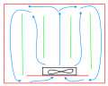
Sorry for the bad drawing. Red=Aluminum sealed enclosure. Blue=air flow. Green = PCBs that are hot with heat sinks.
Black is a fan in the bottom of the enclosure.
Air if forced through the electronics and picks up heat. Air then runs across the top of the enclosure, down the sides and across the bottom of the box. The hot air transfers the energy to the Aluminum enclosure which moves the heat to the room air.
1780933600466.png
We also made a plastic version of the product with vents. We had no failures in the sealed enclosure. The plastic enclosures sucked in dirt, dust and cigarette smoke. In two years the PCBs were covered in a mixture of dust and nicotine. The plastic version had twice the fans and still ran hotter.
 

AnalogKid

Joined Aug 1, 2013
12,241
ron - most of the NEMA 67 enclosures I've had to deal with were either steel (not the greatest thermal conductor) or plastic (worse). Also, laminar boundary layers can form on the inside, reducing heat transfer into the walls. Plus you have no idea what the air flow and turbulence are around the outside of the cabinet, so you can really rely only on radiation for cooling. An aluminum plate with fins pressed into both sides is not cheap, but the thermal transfer is something like 10x.

maria - We have zero information about the problem:

Cabinet size
Internal heat load
MAx internal air temp (which is not the same as the max component temps)
External ambient air temp range
desired delta-T
other

Yes, this type of thermal design requires hard numbers for the heat sources, the heat destination (probably ambient air), available volume for mitigation, min and max temperatures for everything, etc.

The better the numbers, the less margin you have to design in. For a generic cabinet product with unknown internal components, design margins could be 25%.

The best sealed air-to-air systems have fans on both sides of the barrier. One option for the exterior is a fully sealed fan that does not need a filter, or a squirrel cage / rotary impeller fan that does not pull dirty air across the motor.

ak
 

crutschow

Joined Mar 14, 2008
38,689
If needed, along with the internal fan in the sealed cabinet as ronsimpson showed, you could attach fined heatsinks to the outside of the metal cabinet to increase the transfer of heat to the outside ambient.

For more serious heat transfer you could use a heat pipe, which is a passive device that can transfer heat from the inside to the outside with essentially no temperature drop, much lower than solid copper.
Some manufacturers make cabinets with such a cooling system installed.
 

MaxHeadRoom

Joined Jul 18, 2013
30,772
What I used to use was a filtered fan directed inwards with a filtered vent on the other side of the enclosure,, this worked fairly well and kept out any ingress of dust etc.
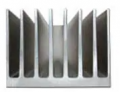
For one that had a number of high heating components I came up with this method below.

Another method was, I obtained this similar extrusion that was the length of the top of the enclosure with each end sealed off, I then made two appertures in the enclosure top at each end of the extrusion,
At one end a fan was fitted that blew across the extrusion and the air exited back into the cabinet on the other end, IOW, circulating fan cooling across the heat sink. AKA air exchanger.
This maintained a sealed enclosure

1780942874876.png
Inverted.
 

AnalogKid

Joined Aug 1, 2013
12,241
Our best "normal" air-to-air was a machined aluminum plate, with graphite fins pressed into the inside and fins machined into the outside. Higher-end-but-not-crazy fans on the inside, and crazy fans on the outside. Both sets of fins were ducted. We also did one with fins inside and outside, with refrigerant as the transfer medium. It had a 1/4 ton compressor the size of a baseball. 19" rack mount, 2U enclosure.

Our absolute best performer was a card cage with eight conduction-cooled boards - to - jet fuel.

ak
 

frannypoo

Joined Jun 4, 2026
14
I spent the last 20 years of my career designing and implementing industrial control systems mounted in various enclosure types (NEMA 7/9, NEMA 12, no enclosure, etc.) located in various environments (from non-classified to Class I, Div. 1; indoors and outdoors, etc). I developed a program that was used throughout the company that calculated heat load based on an enclosure's specific BOM and the resulting deltaT based on expected worst case ambient conditions. This tool allowed us to evaluate how best to address any issues. I'm very much in line with AnalogKid regarding the necessity of generating hard numbers. That said, I would offer the following general info:

1.) Use the least intensive method required to maintain the desired internal enclosure temperature. For smaller enclosures, you might be able to get by with passive conduction/convection. Sometimes going to a slightly larger enclosure can increase the surface area enough to make a difference. If passive isn't enough, and the environment and area classification are amenable, install a small fan and filter. My typical design over the years had a fan at the top of the enclosure and a filter at the bottom. The fan was configured to pull air out of the enclosure - cooler, ambient air in the bottom, warmer air exhausted out the top. But like you point out, filters need to be maintained, so there might be some places where a filter PM just won't happen. The next option is to install a vortex cooler in the enclosure. These can work OK, but are very dependent on the quality of the air/gas supply. If air is used, is it clean, dry, and free of oil? Is enough volume available? If nitrogen or some other gas is used, is enough volume available? Does the gas present a health hazard (asphyxiant, etc.) on its own? The last option in my book would be to utilize an air conditioner. These can be expensive to purchase and operate, require their own PM schedule, and may not be an option in certain industrial environments.

2.) Enclosures mounted outdoors in the open will be subject to solar heat gain. Estimating the exact heat gain is more complicated but is dependent on location. Outdoor enclosures will benefit a lot from being painted white. Another good addition would be to put the enclosure under some type of awning to shield it from direct sunlight. It's amazing how much cooler a white enclosure under an awning can be.

3.) Mount the components that generate the most heat near the top of the enclosure. This should help keep some of the lesser heat generators cooler.

4.) Consider using two smaller enclosures. Put the heat generators in one (with the appropriate heat mitigation equipment) and the lesser heat generators in the other.

5.) Look at the operating temperature range for all of the enclosure's components. The max allowed temperature in the enclosure should not be higher than that specified for the lowest maximum temperature component. For design purposes, I usually used 35C as a desired internal enclosure temperature. This was appropriate for the typical BOM I dealt with, allowed for a modest deltaT without undo cooling accommodations, and kept component MTBFs in a reasonable range.

I've used all of these suggestions at various times over the years. Hope that helps.
 

MisterBill2

Joined Jan 23, 2018
28,053
I put the heat generators lower and the terminal strips in tyhe hot zone. One small fan to assure circulation. AND an aluminum enclosure with no paint.
 

MisterBill2

Joined Jan 23, 2018
28,053
To figure the heat load I would add the "wattage" rating of allof the active components inside the enclosure. I also consider that terminal blocks are not very heat sensitive, and thus can work very well in the hottest parts of the enclosure. On some occasions, for systems with heat-sensitive computers and sensitive ANALOG instruments, actual enclosure "A-C" units were required. That was usually in factory environments that were always HOT. Mostly, metal forging operations. Most other operations could use passive cooling.
 

KayZhao

Joined Aug 18, 2026
3
One sensor near the top of the cabinet, close to the drives, and another near the air inlet or outside the cabinet can be useful. I would record both temperatures together with the machine state or load.

An absolute temperature alarm protects the equipment, but the temperature rise above ambient is also useful for maintenance. If that difference slowly increases under a similar load, it may point to a dirty filter, a weak fan or a change in airflow before the machine actually overheats.
 
Status
Not open for further replies.
Top