Facebook
 Google
 GitHub
 Linkedin

Experimenting with a 1976 Kenwood KA-3500 (40 watts per channel into 8Ω (stereo)) integrated amplifier.
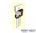
I replaced all 4 original NEC 2SB618+ 2SD588 "batwing" [TB33] pwr trans with new Toshiba 2SC5200 / 2SA1943 which are TO3PL (TO-264) pkg. So they cannot be screwed into orig heatsink w/o modification.
I don't want to go that route just yet.
It may be more educational to experiment with coupling the TO3 to the heatsink w/o extensive mods.
And then, test it out with FLIR thermal camera, finger test, wattmeter (Killawatt), o'scope waveform analysis. The thermal camera is a very useful device, and can give a lot of insight.
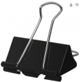
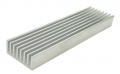
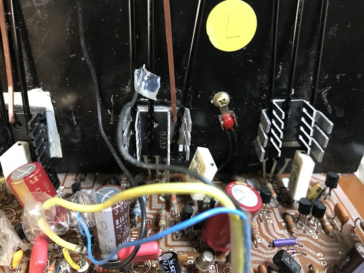
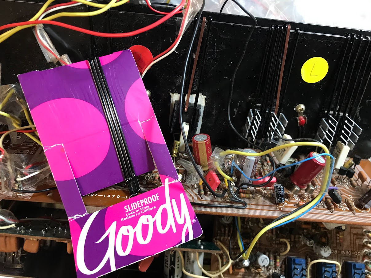
What I've done is use double-sided (insulated) thermal tape to adhere TO3 (TO-264) devices to heatsink. Then I am using several women's long hair pins to compress the TO3 (TO-264) to heatsink (emulating the compression of the single screw that's not being used) . The amount of tensile compressing of each hair pin increases as it spread further apart. So this gives me an opportunity to add smaller heatsink units to the FRONT of the TO3 (TO-264) devices. I'm still playing around. I have not used any thermal compound or thermal tape for the smaller, front heatsinks. I have maximized the number of hairpins I can fit on the width of the TO3.
This approach to dissipating heat seems to be doing okay, but I have not done the usual 10-min full pwr test (just below clipping).
The specs for KA-3500 are 280w from wall at full 40W into 8 ohms.
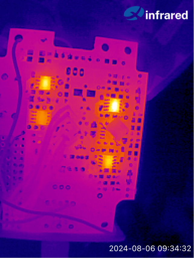
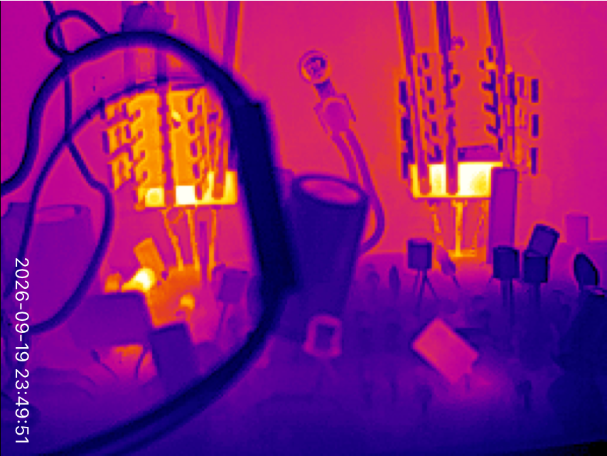
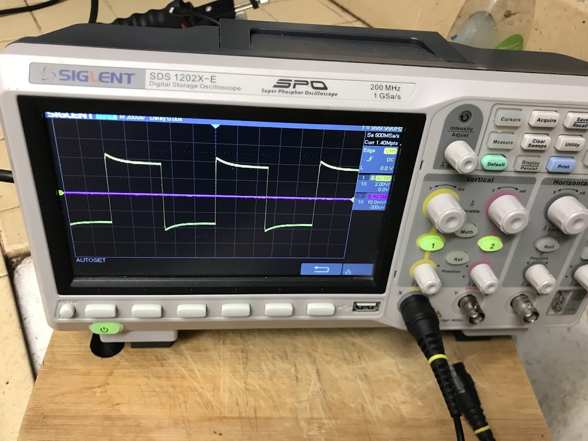
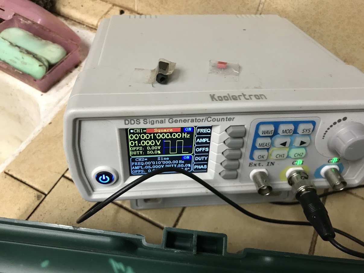
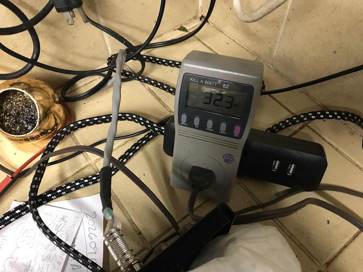
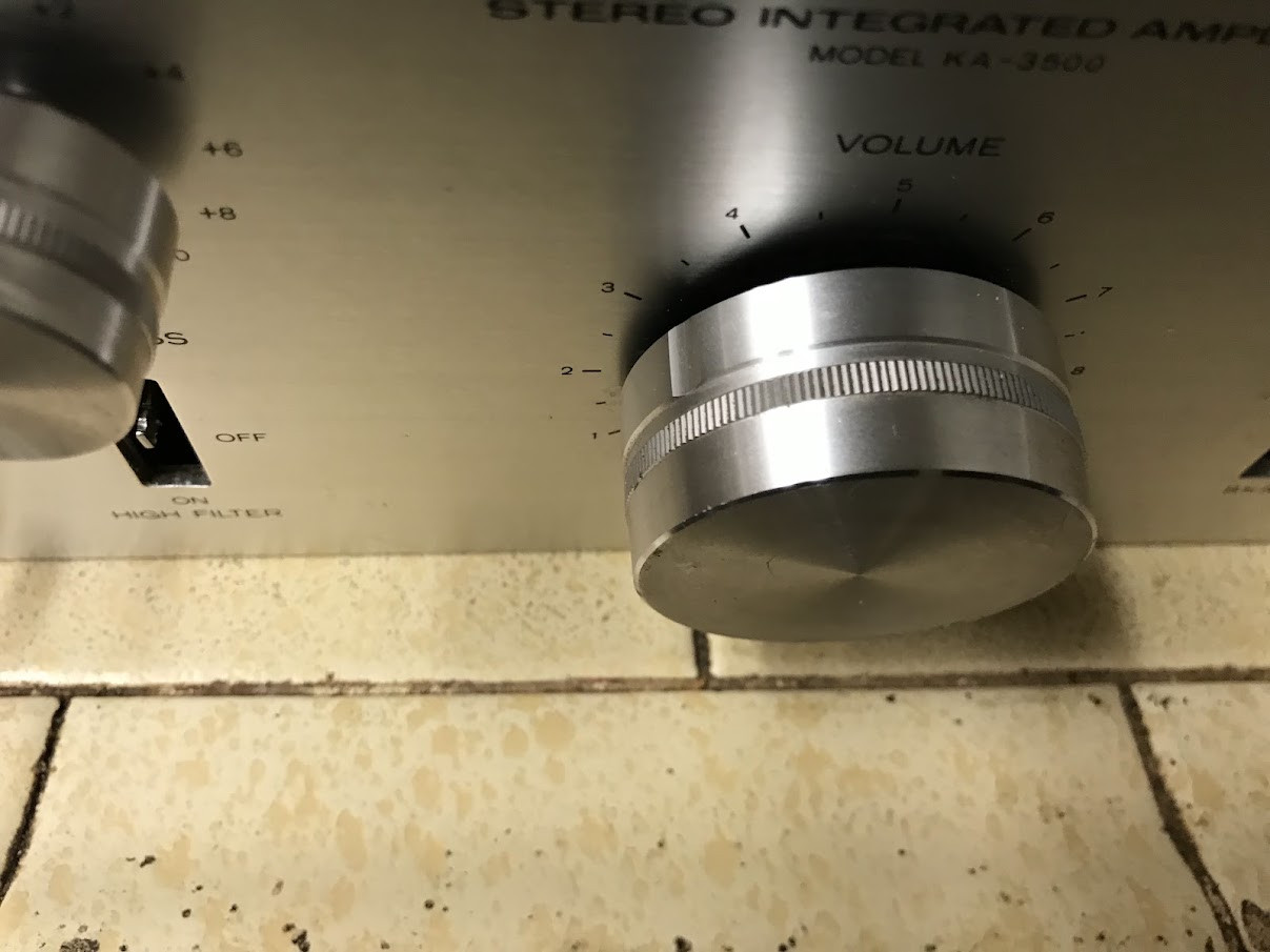
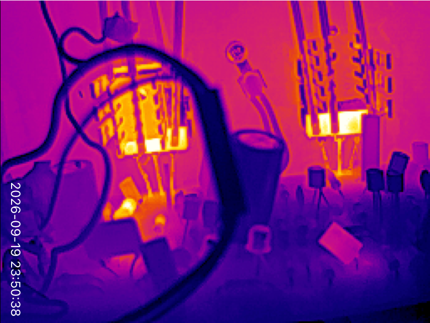
Idle pwr draw of the KA-3500 is about 13W (120 VAC). I have taken the volume up, with 1k sine wave (into 6-ohm) dummy load , with the Killawatt reading about 38W at 120AC mains. The thermal camera can see parts of the TO3 (TO-264) that the front heat sink does not touch. And that is about 160F at the 38W draw.
Perhaps the most interesting thing I've learned from this experiment is how warm the FRONT heat sinks become. (Yes, the the large rear OEM heat sinks get warm, but they are very large.
Questions:
Is the thermal coupling of these pwr transistors meant for ONLY rear heat transfer? Meaning internal die couples ONLY to rear for heat conduction? If so, why does the FRONT of device still get hot (to finger touch or probe/FLIR measurement)?
How tight is the usual screw/bolt (only one is needed to TO3) supposed to be? I assume: It can't be too tight to avoid mechanical damage to stress to silicon wafer.
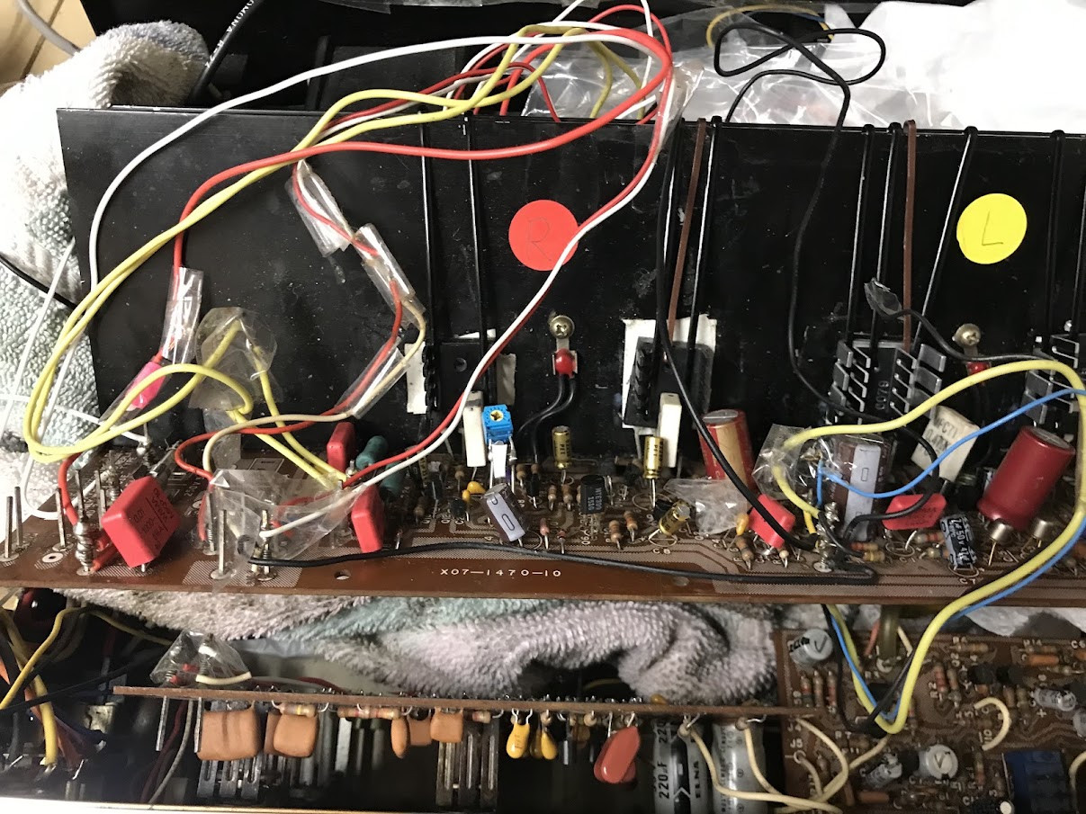
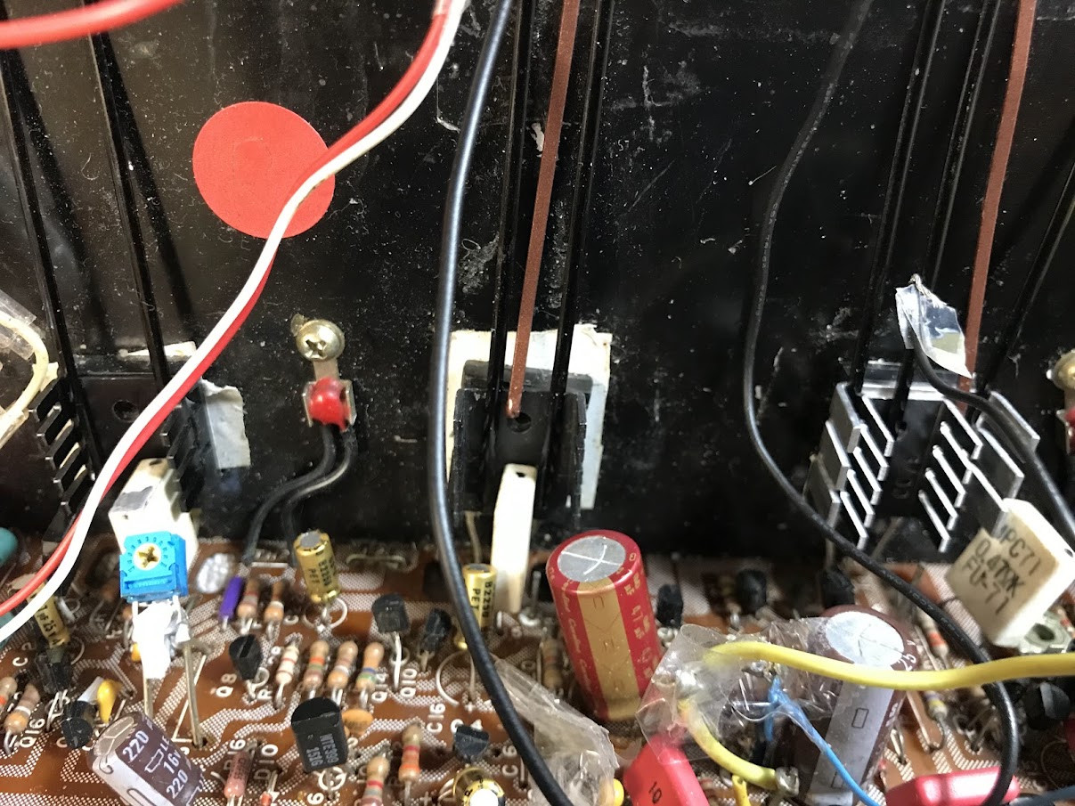
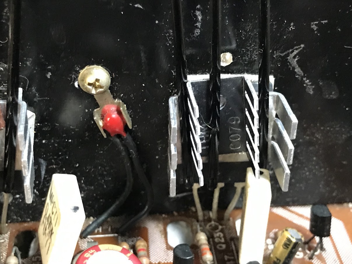
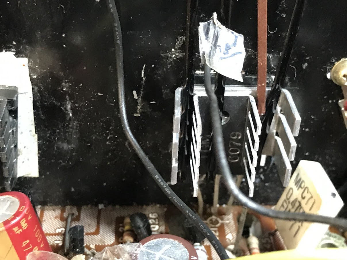
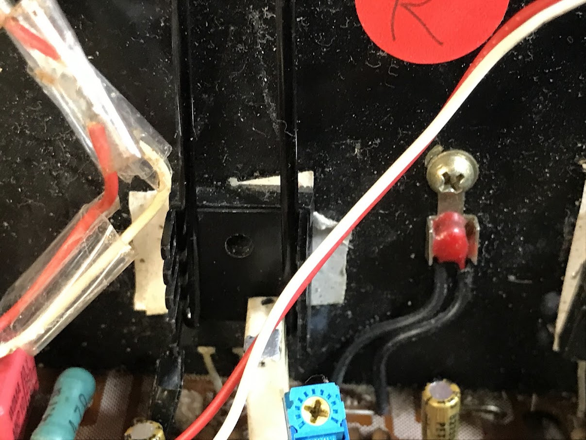
I replaced all 4 original NEC 2SB618+ 2SD588 "batwing" [TB33] pwr trans with new Toshiba 2SC5200 / 2SA1943 which are TO3PL (TO-264) pkg. So they cannot be screwed into orig heatsink w/o modification.
I don't want to go that route just yet.
It may be more educational to experiment with coupling the TO3 to the heatsink w/o extensive mods.
And then, test it out with FLIR thermal camera, finger test, wattmeter (Killawatt), o'scope waveform analysis. The thermal camera is a very useful device, and can give a lot of insight.
What I've done is use double-sided (insulated) thermal tape to adhere TO3 (TO-264) devices to heatsink. Then I am using several women's long hair pins to compress the TO3 (TO-264) to heatsink (emulating the compression of the single screw that's not being used) . The amount of tensile compressing of each hair pin increases as it spread further apart. So this gives me an opportunity to add smaller heatsink units to the FRONT of the TO3 (TO-264) devices. I'm still playing around. I have not used any thermal compound or thermal tape for the smaller, front heatsinks. I have maximized the number of hairpins I can fit on the width of the TO3.
This approach to dissipating heat seems to be doing okay, but I have not done the usual 10-min full pwr test (just below clipping).
The specs for KA-3500 are 280w from wall at full 40W into 8 ohms.
Idle pwr draw of the KA-3500 is about 13W (120 VAC). I have taken the volume up, with 1k sine wave (into 6-ohm) dummy load , with the Killawatt reading about 38W at 120AC mains. The thermal camera can see parts of the TO3 (TO-264) that the front heat sink does not touch. And that is about 160F at the 38W draw.
Perhaps the most interesting thing I've learned from this experiment is how warm the FRONT heat sinks become. (Yes, the the large rear OEM heat sinks get warm, but they are very large.
Questions:
Is the thermal coupling of these pwr transistors meant for ONLY rear heat transfer? Meaning internal die couples ONLY to rear for heat conduction? If so, why does the FRONT of device still get hot (to finger touch or probe/FLIR measurement)?
How tight is the usual screw/bolt (only one is needed to TO3) supposed to be? I assume: It can't be too tight to avoid mechanical damage to stress to silicon wafer.
Last edited: