Power transistor to heatsink (coupling, interface, heat transfer)

Thread Starter

oh_uh_okay

Joined Aug 24, 2025
88
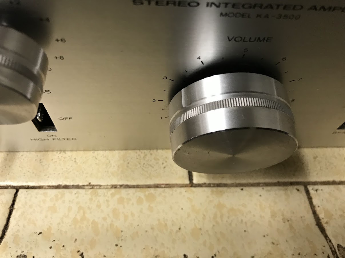
Experimenting with a 1976 Kenwood KA-3500 (40 watts per channel into 8Ω (stereo)) integrated amplifier.
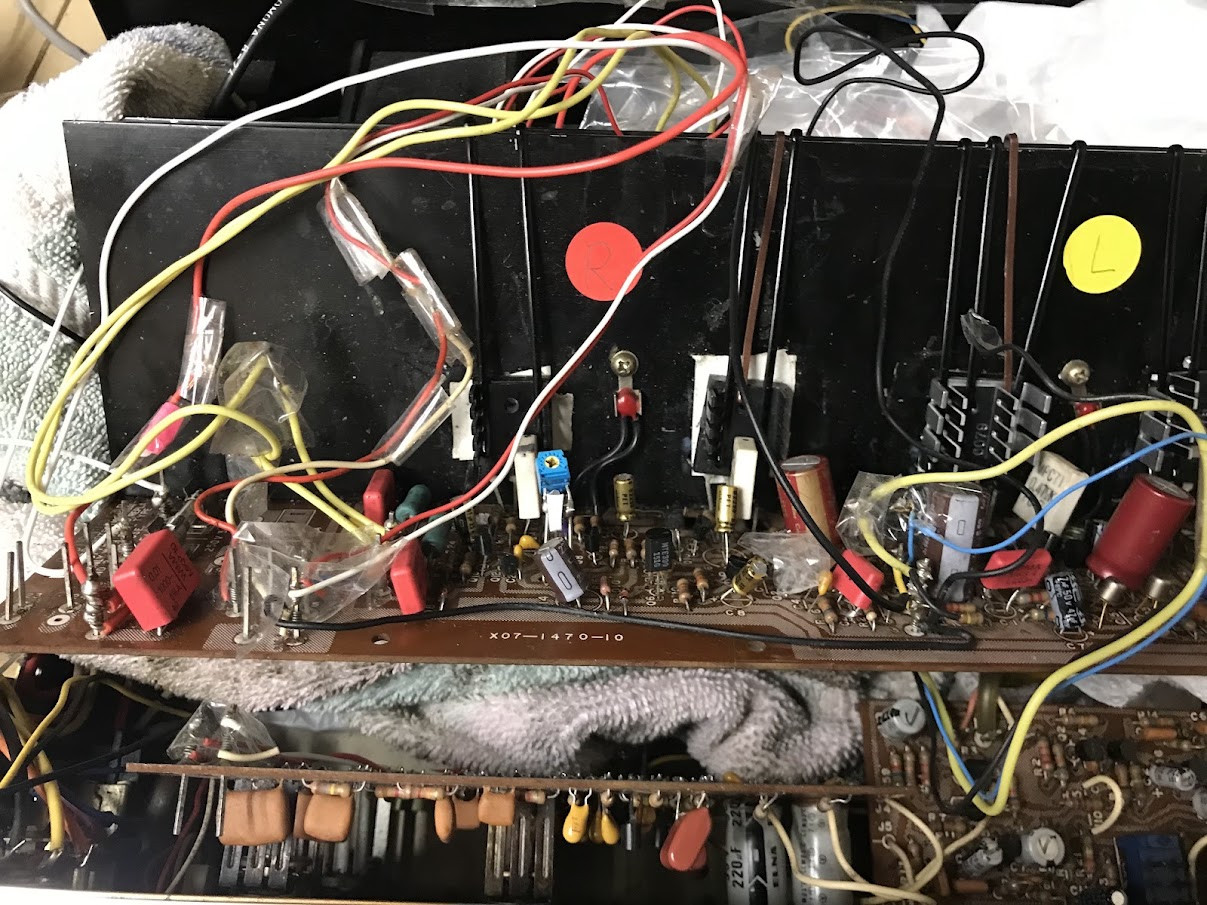
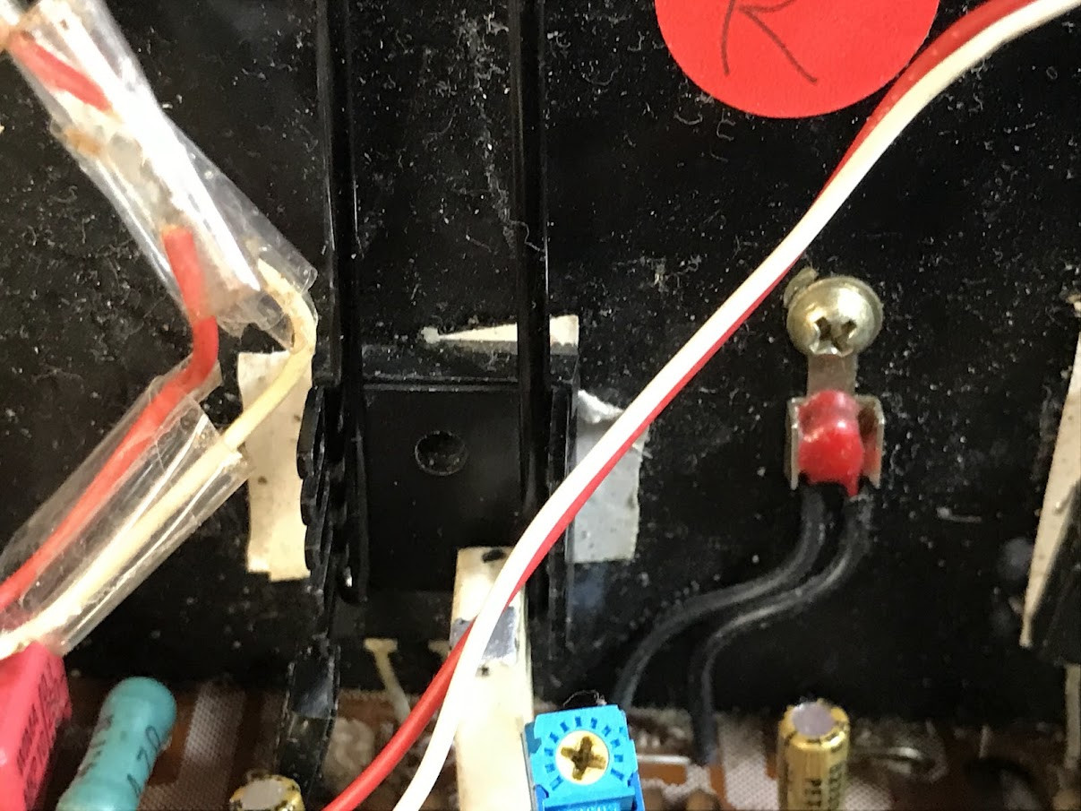
I replaced all 4 original NEC 2SB618+ 2SD588 "batwing" [TB33] pwr trans with new Toshiba 2SC5200 / 2SA1943 which are TO3PL (TO-264) pkg. So they cannot be screwed into orig heatsink w/o modification.
I don't want to go that route just yet.
It may be more educational to experiment with coupling the TO3 to the heatsink w/o extensive mods.
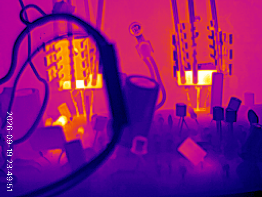
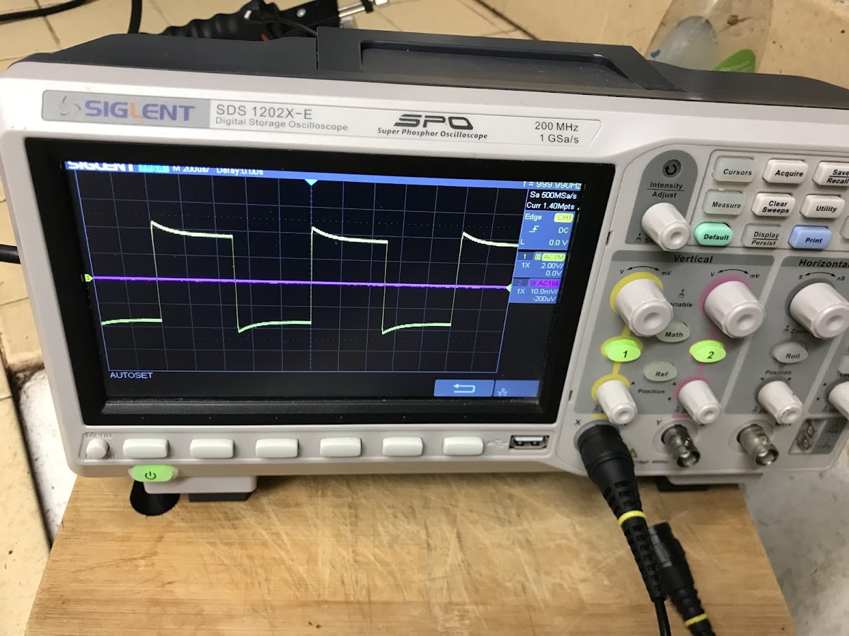
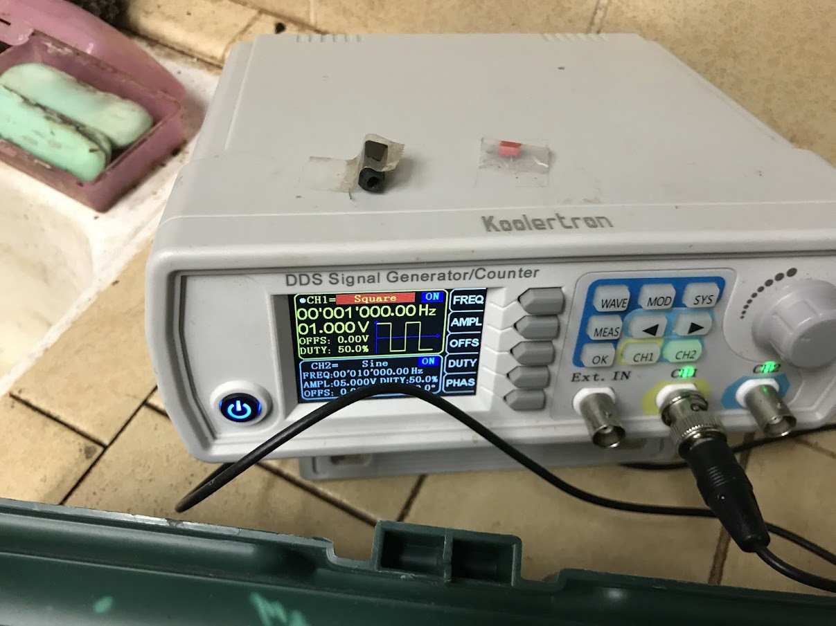
And then, test it out with FLIR thermal camera, finger test, wattmeter (Killawatt), o'scope waveform analysis. The thermal camera is a very useful device, and can give a lot of insight.
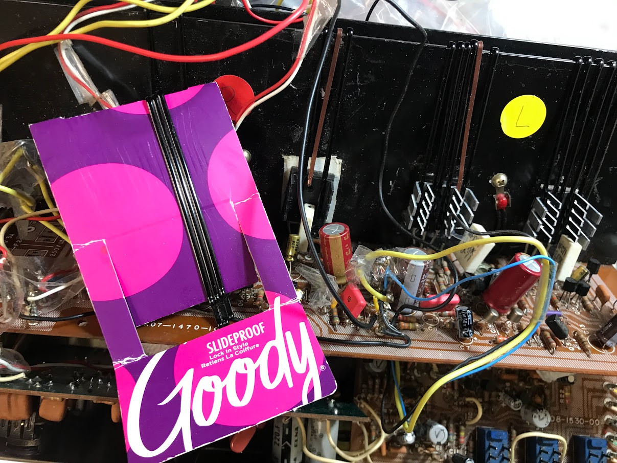
What I've done is use double-sided (insulated) thermal tape to adhere TO3 (TO-264) devices to heatsink. Then I am using several women's long hair pins to compress the TO3 (TO-264) to heatsink (emulating the compression of the single screw that's not being used) . The amount of tensile compressing of each hair pin increases as it spread further apart. So this gives me an opportunity to add smaller heatsink units to the FRONT of the TO3 (TO-264) devices. I'm still playing around. I have not used any thermal compound or thermal tape for the smaller, front heatsinks. I have maximized the number of hairpins I can fit on the width of the TO3.
This approach to dissipating heat seems to be doing okay, but I have not done the usual 10-min full pwr test (just below clipping).
The specs for KA-3500 are 280w from wall at full 40W into 8 ohms.
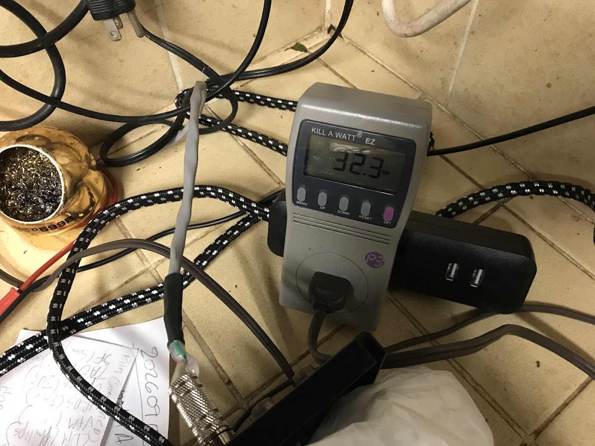
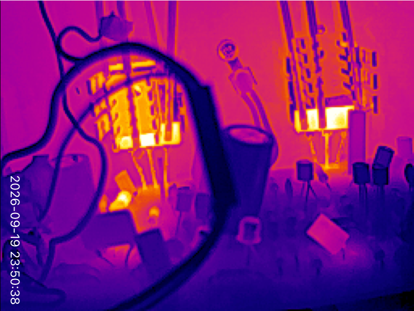
Idle pwr draw of the KA-3500 is about 13W (120 VAC). I have taken the volume up, with 1k sine wave (into 6-ohm) dummy load , with the Killawatt reading about 38W at 120AC mains. The thermal camera can see parts of the TO3 (TO-264) that the front heat sink does not touch. And that is about 160F at the 38W draw.
Perhaps the most interesting thing I've learned from this experiment is how warm the FRONT heat sinks become. (Yes, the the large rear OEM heat sinks get warm, but they are very large.

Questions:
Is the thermal coupling of these pwr transistors meant for ONLY rear heat transfer? Meaning internal die couples ONLY to rear for heat conduction? If so, why does the FRONT of device still get hot (to finger touch or probe/FLIR measurement)?
How tight is the usual screw/bolt (only one is needed to TO3) supposed to be? I assume: It can't be too tight to avoid mechanical damage to stress to silicon wafer.
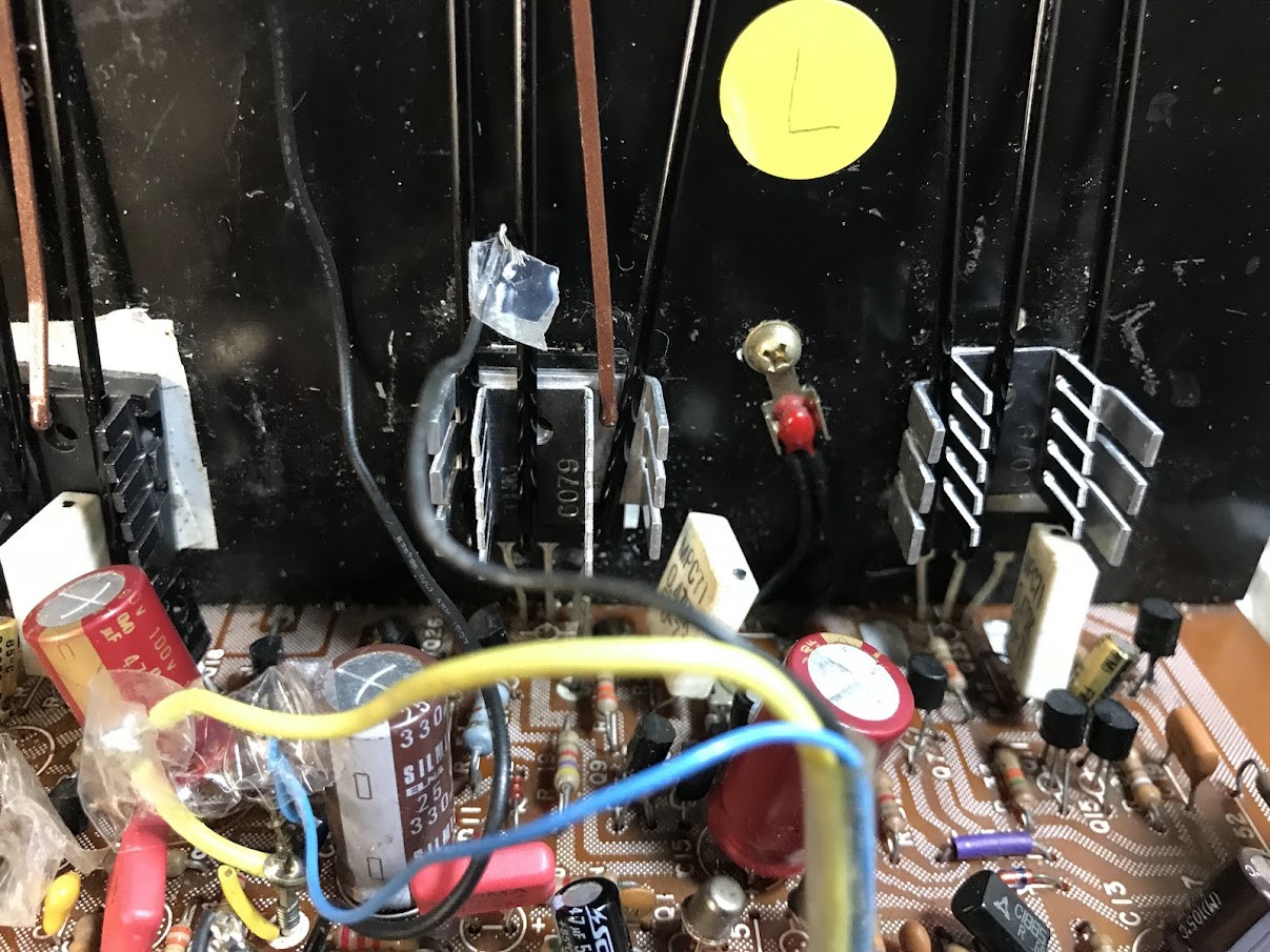
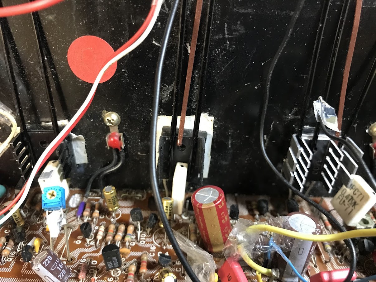
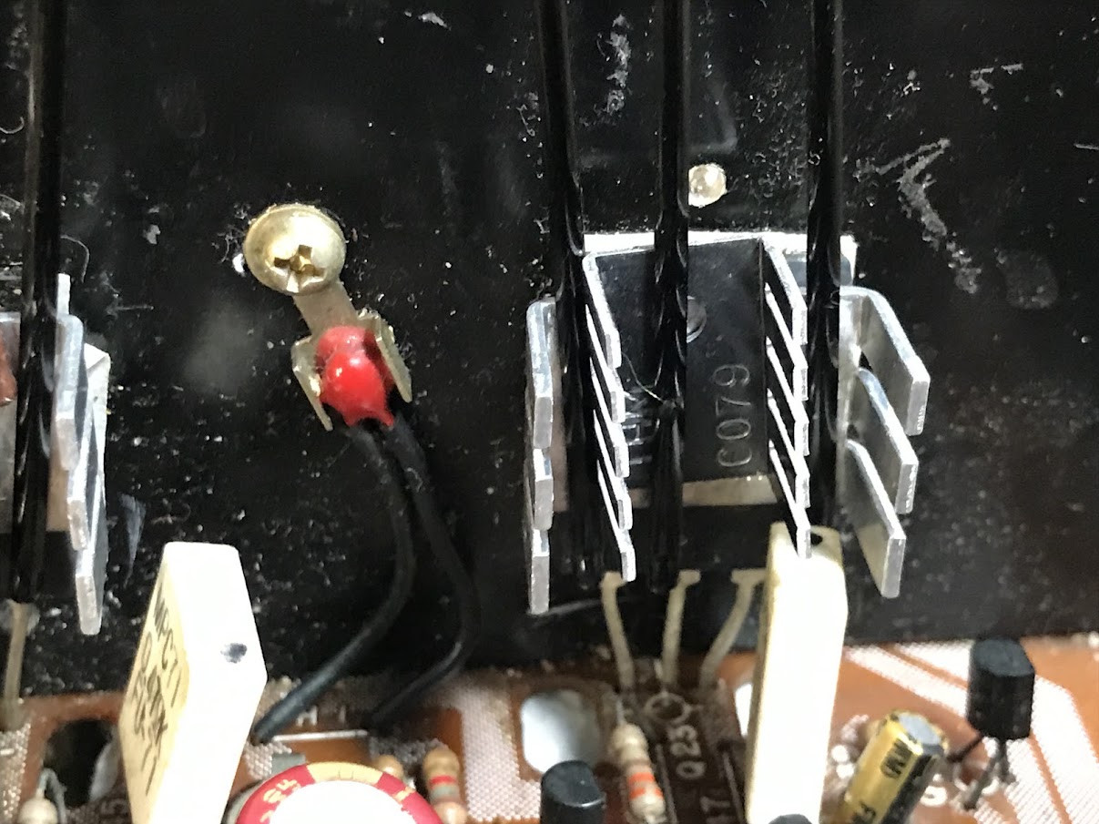
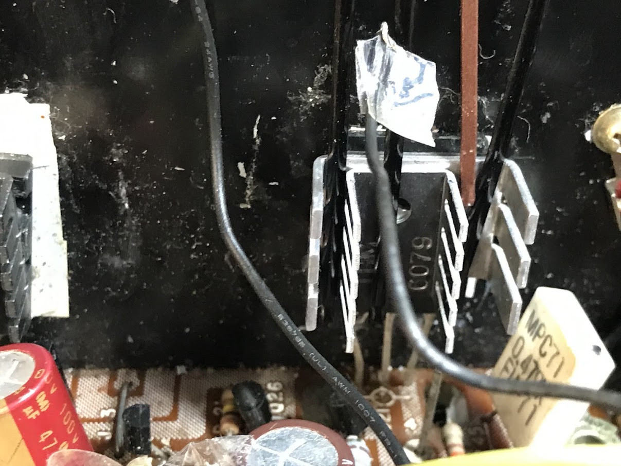


Last edited:
When you use a thermal camera, just remember that different materials have different thermal emissivity. From the top of my head, brushed natural aluminum is a poor thermal emitter. The thermal readings will be inconsistent. If you can, substitute those with black anodized heat sinks.
 
Last edited:
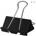
You can use large binder clips such as this:
Screenshot 2026-09-20 at 9.42.39 AM.png
As long as you don't use too much force. Excess force can cause thermal grease to be squeezed out and reduce the amount of heat transfer.
why does the FRONT of device still get hot?
Same reason why the base of a lightbulb gets hot. Thermal energy moves from the higher energy to areas of lower energy. The heatsink allows that energy to radiate to atmosphere. But the whole device still gets hot. Surface, leads, solder, circuit board - etc. Heat always moves from the higher level to the lower level. Using a clip like what's shown will also act as a heat sink to some degree.

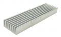
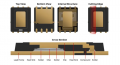
This type of heatsink is designed to go on TOP of an IC. As for the internal construction of an IC, I've seen many, some may have the chip mounted on the top of the IC internally.
Screenshot 2026-09-20 at 9.49.17 AM.png
Nevertheless, if a chip gets hot - a heatsink can draw it away and radiate it to atmosphere. Other sorts of heatsinks exist that are oil filled and piped away to a fan to further accelerate dissipation of heat.
 

crutschow

Joined Mar 14, 2008
38,787
As long as you don't use too much force. Excess force can cause thermal grease to be squeezed out and reduce the amount of heat transfer.
Not true.
You want a minimum layer of thermal grease for maximum heat transfer, since the grease has a much higher thermal resistance than the metal (but lower than air).
The grease is just to fill in any small air gaps between the transistor and the heatsink.
Any grease more than the minimum to fill those gaps, will reduce the heat transfer.
 
Last edited:

Thread Starter

oh_uh_okay

Joined Aug 24, 2025
88
You can use large binder clips such as this:
View attachment 371523
As long as you don't use too much force. Excess force can cause thermal grease to be squeezed out and reduce the amount of heat transfer.

Same reason why the base of a lightbulb gets hot. Thermal energy moves from the higher energy to areas of lower energy. The heatsink allows that energy to radiate to atmosphere. But the whole device still gets hot. Surface, leads, solder, circuit board - etc. Heat always moves from the higher level to the lower level. Using a clip like what's shown will also act as a heat sink to some degree.

This type of heatsink is designed to go on TOP of an IC. As for the internal construction of an IC, I've seen many, some may have the chip mounted on the top of the IC internally.
View attachment 371527
Nevertheless, if a chip gets hot - a heatsink can draw it away and radiate it to atmosphere. Other sorts of heatsinks exist that are oil filled and piped away to a fan to further accelerate dissipation of heat.
The large binder clip would be good, but that large and tall orig heatsink does not allow for much clearance for anything other than the hair clips.
BTW:
Some photos above are not showing so trying again:


Thread Starter

oh_uh_okay

Joined Aug 24, 2025
88
So what about the FRONT of the device, be it a transistor, regulator, etc? As I asked in the OP:
Is the thermal coupling of these pwr transistors meant for ONLY rear heat transfer? Meaning internal die couples ONLY to rear for heat conduction? If so, why does the FRONT of device still get hot (to finger touch or probe/FLIR measurement)?
 

Thread Starter

oh_uh_okay

Joined Aug 24, 2025
88
Hello,

The images still do not show.
Are you using an external picture server?
Please upload the pictures to the forum.

Bertus
Not sure why some show and some don't. But in PREVIEW mode, they show just fine.
BTW: No way. I'm not uploading any of my IP to this greedy forum so they can claim it as their own.
 
The views all show on my HP win7 computer!
Devices intended to have a heatsink certainly have a PRIMARY heat-transfer surface, but all of the other surfaces can also provide heat transfer out.
 

WBahn

Joined Mar 31, 2012
33,176
Not sure why some show and some don't. But in PREVIEW mode, they show just fine.
BTW: No way. I'm not uploading any of my IP to this greedy forum so they can claim it as their own.
It appears that you don't understand the way that forums work or the User Agreement that you agreed to when you joined.

Forums like this are for collaborative discussions for the benefit not just those participating in that particular discussion, but for the entire community, including people well into the future. They are NOT just a service where you can get free help from strangers on the Internet (just who is being greedy is you think that's the case?).

Imagine that you did a search for your problem and it pulled up a discussion from ten years ago that had exactly the answer to your question, but that answer was in a diagram that was no longer available because it was linked to some photo server that went out of business several years ago. I imagine you'd be upset and complaining because the forum wasn't doing a good job of archiving the content you needed. But the only way the forum can do that is if the content you post is located on our servers so that it CAN be properly archived for future reference.

No one here is going to claim it as our own, and posting a picture linked to a third-party server instead of uploading it here wouldn't prevent that anyway.

Look at the User Agreement and you'll see the clause, " You are granting us with a non-exclusive, permanent, irrevocable, unlimited license to use, publish, or re-publish your Content in connection with the Service. You retain copyright over the Content. "

That basically means that once you post anything here, it becomes part of the forum archive. But, other than that, you retain copyright so we cannot, legally, claim it as our own.
 

Thread Starter

oh_uh_okay

Joined Aug 24, 2025
88
The views all show on my HP win7 computer!
Devices intended to have a heatsink certainly have a PRIMARY heat-transfer surface, but all of the other surfaces can also provide heat transfer out.
14 images should show in total. But three show "X" on my end. I looked at the postimg urls of all image, tried to pick out some sort of inconsistency, but no matter how I arrange, the same three are "X'd" out. I can see ALL images in Preview mode. Here are two of the blocked images:
https://postimg.cc/K3YbFjLT

https://postimg.cc/hQGngvxj

About the primary heat-transfer surface...
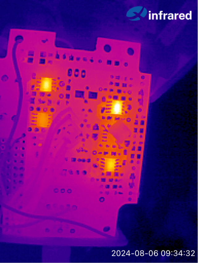
I ran into this issue with SOIC 8-pin LMH6321 current buffers for a portable DIY headphone amp I built many years ago. If the environment got too warm (outside in a heat wave), I would get loud distortion.
Measured buffer temps at 130F (idle) when room temp at 75F.
I did use same thermal tape and some flat copper to heat sink. And this fixed the issue.
(Below is a before-fix thermal image)
 
Last edited:

kiroma

Joined Apr 30, 2014
185
No one mentioned, so I'll mention: your scrope probe needs adjustment. There's a screw on the BNC connector that you can rotate to better adjust for a critically dampened transition between the low and high levels of your square wave. The 5 V 50% duty on every scope is to calibrate for that. The screw tighten on the cable creating less distance between the center and the outer side, so it can change the capacitance, thus changing the behavior. I never took the time to understand it, I just calibrated it.
Here is why and how

Edit: fixed typo
 
Last edited:

crutschow

Joined Mar 14, 2008
38,787
There's a screw on the BNC connector that you can rotate to better adjust for a critically dampened transistion between the low and high levels of your square wave.
All the 10X scope probes I've used have the adjustment screw on the probe, but apparently some have it on the BNC connector.
 

kiroma

Joined Apr 30, 2014
185
So what about the FRONT of the device, be it a transistor, regulator, etc? As I asked in the OP:
Is the thermal coupling of these pwr transistors meant for ONLY rear heat transfer? Meaning internal die couples ONLY to rear for heat conduction? If so, why does the FRONT of device still get hot (to finger touch or probe/FLIR measurement)?
My attempt to answer (I think it's correct):
Yes, the rear is where the chip have low thermal resistance to the package.
Why does the front still get hot? Because it conducts heat and can't dissipate well through the front. You can crush a transistor like that and see for yourself that the front is pure epoxy. Epoxy doesn't conduct well thermally. All your effort with frontal heatsink is probably minimal advantage to the system.
Also, you never put a scale next to the images, so they are almost meaningless in terms of value of temperature. If the hot spot is 100 °C and the coolest spot is 0 °C would be the same image (almost, hard to distinguish) as 50° C hot spot and 25 °C coldest spot.
 
Top