Powering a photomultiplier tube, connecting it to Arduino with voltage amplifiers and resistors; to build a cosmic ray detector wit scintillation

Thread Starter

mirandasofty06

Joined May 6, 2026
1
Hi I am Miranda and I am a sophomore in college. This past year I have been completing a class to do research in Alaska and I may have taken on more than I first thought. I am wanting to build a cosmic ray detector using a photomultiplier tube, scintillator and Arduino, that is portable. While the trip has passed, I am still wanting to complete this project but the problem is that I do not have much experience in electronics. My professor is currently working on the pmt powering piece of the project but I wanted to see if anyone had done this before, knew anything about pmts, or could be of help in any way.

1. Powering the PMT
- the photomultiplier tube needs about 900-1000volt with a low current. The circuit we are trying to build using a 555 timer and a transformer to amplify about 9V along with a series of capacitors and resistors to get the voltage up to where it needs to be. I believe my professor has a circuit planned out and is going to build it soon. The pmt I am using is a RCA 931- A: https://frank.pocnet.net/sheets/049/9/931A.pdf. I also have some

2. The next piece of the problem is wiring the pmt to the high voltage circuit with a voltage divider using 1Mohm resistors on the pegs of the pmt. like in this article: https://www.dynode.nl/pmts-and-scintillation-probes/.

3. We are wanting to possibly use a transimpedance amplifier circuit to convert current to voltage to data recording. https://www.ti.com/lit/an/sboa268b/sboa268b.pdf?ts=1770258290831

4. We are trying to use a arduino uno microcontroller to record data and run code for the pmt.

I need help trying to put all these pieces together for the entire circuit and help understanding how these pieces work and behave. If anyone know anything, has done this before; any help will be much appreciated. I can give any more information you may need to help out, also. I am only a sophomore in college and have very little experience outside of class. I ma wanting to get this done soon so thatI can take data and then present on it at a conference in December. I keep looking for article online, and while I have found some good ones- it's just not enough. Thanks so much!
 

MrChips

Joined Oct 2, 2009
34,767
A PMT (photomultiplier tube) detects light. This is where the scintillator comes into play. When a high energy particle hits the scintillator, light is produced which can be detected by the PMT. There is a wide range of high energy particles that are detected by this method, from X-rays, to gamma rays and cosmic rays. The problem here is differentiating the different particles with this setup.

One technique that is used to detect cosmic rays is the coincidence method. Two radiation detectors are used, commonly one is enclosed by the other. Cosmic rays have very high energy and hence will penetrate both detectors. The detection system has to be fast enough to record the hit as occurring simultaneously, hence in coincidence. This is beyond the capabilities of an Arduino system.
 

Irving

Joined Jan 30, 2016
5,107
Hi Miranda, welcome to AAC.

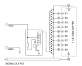
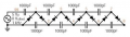
Getting to 900-1000v from a 9v battery is a non-trivial exercise. Here's a commercially available 'base' for a PMT that incorporates the HV supply and output circuitry (disclaimer: may not fit your PMT). The company that supply it have a useful handbook on using PMTs, attached here. They suggest a Cockcroft-Walton multiplier for the HV supply - which was also my first thought after reading your intro - for better stability and linearity as shown below (from section 5.1.8 in the document), but ignore the crude transistor oscillator, there are better ways to do that (and not a 555 either). For efficiency you need Vin to be as high as possible - not sure what sort of 9v battery you were envisaging, but a PP3 probably won't deliver the goods if you're looking for any reasonable run times.

1778230776056.png
 

Attachments

Irving

Joined Jan 30, 2016
5,107
Some further thoughts, following on from @MrChips comment re Arduino. I concur, the Arduino is glacial compared to the PMT response.

Are you just trying to count events or do you need to measure the size of the pulse? if the latter, based on the PMT datasheet stating anode pulse rise and transition times, you'll need an ADC capable of sampling in around 5nS to get sufficient accuracy. That's a 180MHz+ sampling rate, doable, but not with an Arduino! An Arduino may well feature in the user interface, and on the control and data management side of things, but not in data acquisition - that requires some specialist engineering.
 

MrChips

Joined Oct 2, 2009
34,767
Firstly, let us look at the HV power supply. The PMT needs about 50 μA @ 1000 V.

There are two ways to achieve this. You can buy a modular, off-the-shelf HV PSU.

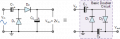
You can also DIY a HV supply, typically using a voltage doubler circuit. This consists of AC input and a cascade of capacitors and diodes.

1778247092399.png

1778247034115.png


At the final output, you will need a HV rectifier and HV filter capacitor that can handle in excess of 1000 V.

I have seen HV circuits using 555-timer circuits. The 555-timer runs in astable oscillator mode between 7-10kHz and the output drives a power transistor. The output is fed into an AF output transformer in reverse mode to generate about 200V. This is followed by three voltage doubler stages.
 

MrChips

Joined Oct 2, 2009
34,767
Now, let us examine the radiation detection part of the problem. You specifically said "cosmic ray detector" and did not make a distinction between gamma ray and cosmic ray.

The rate of cosmic rays hitting a 1-inch cube detector is very low, about once a minute. Compare this with gamma rays from natural surroundings; you can detect rates of about 100 counts per second. Are you certain that you want to detect only cosmic rays and not gamma rays in general?

There are two methods of radiation detection, (a) pulse counting and (b) energy or pulse-height analysis.

(a) You can count the number of events detected by the PMT. For this you do not need amplification. You can send the PMT output to an analog comparator and then count the pulses exceeding the comparator threshold voltage. At low count rates, you can use the Arduino to count pulses. By raising the threshold voltage, you can reject low energy radiation and only count particles of higher energies.

(b) For pulse-height analysis, you need a peak sample and hold circuit. Then you can use a slow conversion ADC to digitize the output voltage. Again, at low rates the Arduino might be just able to keep up. With pulse-height analysis, you can collect an energy spectrum, and with high enough resolution, you may be able to determine the source of the radiation.

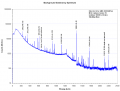
Here is an example of a typical background spectrum at high resolution. The highest peak is from naturally occurring potassium.
(Note that this energy spectrum was acquired using a high purity germanium detector. Such high resolution is unattainable with a scintillation detector.)

1778250122781.png


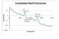
In comparison, here is a typical background energy spectrum collected with a NaI scintillation detector.NaI background spectrum.jpg
 

Irving

Joined Jan 30, 2016
5,107
Impressed with your knowledge of PMT. I've only had a passing involvement in the distant past experimenting with a couple as an EMP detector, the random idea being to detect an EMP that wasn't obviously immediately damaging but to make service personnel aware that things may not be working as well. Whether it worked, or would have worked, I have no idea. I was just tasked with powering it up.

he output is fed into an AF output transformer in reverse mode to generate about 200V. This is followed by three voltage doubler stages
In the clip I showed the idea is that the generator produces 100v, and each doubler adds 100v so maintaining a precise voltage differential between dynodes and up to the anode. Thus the originating voltage can be varied to adjust the anode volts around 900v +/- 100v and the dynodes stay in step
 

MrChips

Joined Oct 2, 2009
34,767
Impressed with your knowledge of PMT. I've only had a passing involvement in the distant past experimenting with a couple as an EMP detector, the random idea being to detect an EMP that wasn't obviously immediately damaging but to make service personnel aware that things may not be working as well. Whether it worked, or would have worked, I have no idea. I was just tasked with powering it up.


In the clip I showed the idea is that the generator produces 100v, and each doubler adds 100v so maintaining a precise voltage differential between dynodes and up to the anode. Thus the originating voltage can be varied to adjust the anode volts around 900v +/- 100v and the dynodes stay in step
No. It is called a voltage doubler. Each stage doubles the voltage.
Hence, if you start with 100 VAC, you end with 800 VAC after three stages.
 

Irving

Joined Jan 30, 2016
5,107
No. It is called a voltage doubler. Each stage doubles the voltage.
Hence, if you start with 100 VAC, you end with 800 VAC after three stages.
Hmmmm, its been a while since i played with one... but that makes no sense then having a doubler every dynode? My understanding is the dynodes should all have equal voltage differences.
 

joeyd999

Joined Jun 6, 2011
6,269
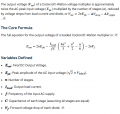
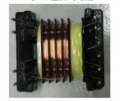
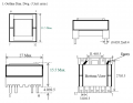
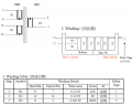
I use a small flyback transformer to generate 1800VDC from 2.5 to 3V for one of my products. At low uA output, this isn't really a major problem. It just requires a custom transformer:

Screenshot From 2026-05-08 16-35-45.png

Screenshot From 2026-05-08 16-31-14.png

Screenshot From 2026-05-08 16-35-35.png

With a feedback winding, it's pretty easy to stabilize the output voltage.
 
Top