Facebook
 Google
 GitHub
 Linkedin
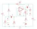
Hi. This is @Audioguru again's electret mic circuit (more/less). It runs on 9v and powers an electret mic putting the audio signal at Vcc/2 into the single sided op amp (TL072), and has a potential gain of 11.

If I wanted to use the same TL072 in a differential configuration at +/- 15v, what would I change? I shouldn't need to bias the input do I? I probably don't want 15v on an electret, something like 4-6v maybe?
Thanks!
If I wanted to use the same TL072 in a differential configuration at +/- 15v, what would I change? I shouldn't need to bias the input do I? I probably don't want 15v on an electret, something like 4-6v maybe?
Thanks!