I saw that but in previous comments, the TS mentions 2kHz when they started the thread :
"
Good Day,
I need help in making a MOSFET switching circuit for switching the + ve side of the supply to load wire and not the GND wire. The trigger signal will be about 3.5 Volts PWM from a Raspberry Pi.
The load Voltage is 12 Volts DC and maximum current is 5 A. The switching frequency will be upto 2 kHz. "
Still I am not sure why you insist on using P-Channel MOSFET which are hard to find and expensive. In circuit designing, you do not use a P-Channel MOSFET unless you have no other option. Could you clarify why you are not using a N-Channel MOSFET and put the load across the drain of that?
I did read thru comments and I figured you want to "observe the change in the magnetic field" but I could not understand it. Best of luck with your project. In case you decided to use the topology I provided , a 22Ω to 47Ω gate resistor is recommended.
Yes I know its hard to understand, actually I am using all components like electromagnets in series and also rodin coils with specific winding patterns inbetween components and using pulsed currents to study their effect. The project is a big one and the more I go into it the more I might start to sound like a con, so I keep the details covered and only the circuit functions in the discussion so it wouldn't cause much confusion.
Yes I understand not many applications are using P Channel MOSFETs for switching, and I dont suppose they are expensive but still hard to find the right combination of circuit components to put it into use for working. But in my project I see there is a change in using P channel MOSFET positive side switching as against low side switching which is beneficial so I wish to pursue that. I am not running practical machines like motors or moving parts, the aim is to study magnetic fields and their healing properties.
Yes I like to test the topology you provided. In the 12 Volt circuit sghioto provided, it was working fine. But at higher voltage the components and circuit need to be modified.
I have chosen the following components for the circuit shown
instead of Q1 and Q2 (2SC5876U3 NPN, SOT-323, 60V 0.5A, Medium Power Transistor)
If that is what you have on hand, but that is overkill for a totem pole driver. MOSFETs are voltage driven (as opposed to BJTs which are current driven). If you want to order it, I would recommend
The Small Pair (TO-92 package)
NPN: 2N5551
PNP: 2N5401
150V, 600mA
Costs = pennies, fits= anywhere.
I received the components I made the below circuit and tested it just now.
Initially it was all working fine. I tried at 0.1 Hz which is 5 seconds ON and 5 seconds OFF. It switched correctly for 4 to 5 times then the current output was steady, there was no switching after that. I removed the board and checked it, I found that the Q3's terminals 2(base) and 3(collector) are shorted.
Is there any modification that can be done before changing that transistor with a new one? May be a resistor needs to be added in the circuit.
Also I have one other doubt. I am using this SMD diode for D1 specified in the circuit:
BZX84C10-Slkor-SOT-23 Zener Diodes ROHS
It is too small should I use a higher power rated diode.
After some thought I realized that such a resistor would reduce the signal fall time, so I suggest the circuit as modified below, with the Zener moved to the drive transistors to limit the MOSFET Vgs (blue trace).
Note that it's problematic to use a transistor at its max voltage rating.
It should be derated by 10-20%, so for a 60V supply they should have a max rating of 70-80V (which I did not show in the sim).
I received the components I made the below circuit and tested it just now. View attachment 364579
Initially it was all working fine. I tried at 0.1 Hz which is 5 seconds ON and 5 seconds OFF. It switched correctly for 4 to 5 times then the current output was steady, there was no switching after that. I removed the board and checked it, I found that the Q3's terminals 2(base) and 3(collector) are shorted.
Is there any modification that can be done before changing that transistor with a new one? May be a resistor needs to be added in the circuit.
Also I have one other doubt. I am using this SMD diode for D1 specified in the circuit:
BZX84C10-Slkor-SOT-23 Zener Diodes ROHS
It is too small should I use a higher power rated diode.
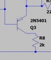
Hello. I am sorry to hear that Q3 died. It was definitely a huge oversight by me as I overlooked the fight between Q3 and D1 that occurs during the switching which @crutschow pointed out. The solution is either getting a stronger PNP (not really needed) or add a 2k resistor between the collector of Q3 and ground. For the speed the you double emphasized (5 seconds off 5 seconds on , which nearly all of us misinterpreted ) the marginal fall time should not be any problem. Only at 50k speed might be any issue but at 0.1 Hz it is negligible. The resistor needs to be at least 1W. You can parallel five resistor with 10k and 1/4W to het 1.25W resistor with 2k impedance
In addition, I mentioned earlier that all those part numbers are just what was available in Spice and NOT necessarily a MUST go to. You are 100% correct. Any zener 12 v rated 1/2 watt will do it and soldering /breadboarding is not going to be difficult like that SMD. Best of luck with your project
After some thought I realized that such a resistor would reduce the signal fall time, so I suggest the circuit as modified below, with the Zener moved to the drive transistors to limit the MOSFET Vgs (blue trace).
Note that it's problematic to use a transistor at its max voltage rating.
It should be derated by 10-20%, so for a 60V supply they should have a max rating of 70-80V (which I did not show in the sim).
For the speed the you double emphasized (5 seconds off 5 seconds on , which nearly all of us misinterpreted ) the marginal fall time should not be any problem. Only at 50k speed might be any issue but at 0.1 Hz it is negligible.
No problem at all, anything new we try it out for the first time, it will always have something to fix so we can learn and correct it.
Thanks to all for your advice and the topologies.
I am testing the circuit at 0.1 hz. Because at that frequency I can clearly check the parameters of current and voltage without an oscilloscope. Then I use it for up to 2000 Hz. I hope I am clear.
Yes I am using 1 Watt resistors on the MOSFET side and the PWM side I use 0.25 watt resistors. The transistors are rated for 150 Volts.
You are most welcome. Just a quick recap: a powerful (1.5 watt) resistor with around 2k impedance gives enough power to get the -10v to the gate of your MOSFET without shorting your PNP transistor. Just a reminder, if you are aiming to increase the frequency to 10kHz and above, that small curve at the top left corner of peaks, will become an issue of MOSFET getting hot. But there are other solutions which will not work with such low frequency. They use a "bootstrapping " capacitor that needs to be filled up rapidly. In such cases, you can ditch P-FET and use N-FET for the high rail with a "high side gate driver" and these ICs are not very pricy
This video is worth watching 3 High Side MOSFET Drive Circuits
tips if you shop from AliExpress
1-Store's reputation (4.8 and above)
2-Store's years of service (in this case more than 11 years)
3-Store's speciality: If they are professional sellers, or sell everything from shoes to ICs
4-The reviews and the orders (customer feedback)
They use a "bootstrapping " capacitor that needs to be filled up rapidly. In such cases, you can ditch P-FET and use N-FET for the high rail with a "high side gate driver" and these ICs are not very pricy
This video is worth watching 3 High Side MOSFET Drive Circuits
I havent tried out the crutschow's modified Zener moved to the drive transistors circuit yet. I am waiting for any other changes that may be suggested in that circuit then I will try it out.
Without that modification I used a 2.2 k resistor between the collector of Q3 and ground. This is what happened:
It worked perfectly for about 3 to four minutes without any issues. Then the switching stopped. Here is what I found. The diode is shorted and the source and drain of the MOSFET is shorted. Think we are missing something here.
Will wait for crutschow to finalise his modification if any. Then will try it out.
 Facebook
 Google
 GitHub
 Linkedin