Facebook
 Google
 GitHub
 Linkedin
Hi,
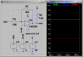
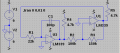
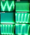
When integrating the square wave of a two transistor multivibrator the resulting triangle wave slowly runs of to the positive or negative power rail depending on reference voltage (please refer to astable tri.png). I'm guessing this is due to the lack of feedback from the integrator back to the multivibrator. In contrast the attached opamp tri.png doesn't have this problem, probably because it has feedback.
Is there a way to apply feedback from the output of the opamp integrator to the multivibrator? I tried inserting the output of the opamp through a resistor into various points in the multivibrator without success.
P.S. I understand that the opamp in opamp tri.png should actually be a comparator but I can't find any push-pull comparators that are through-hole and accept more than 7V supply voltage. At higher frequencies the slew rate of the opamp square wave generator becomes noticeable making the trianlge no longer linear. This is why I'm trying out a discrete multivibrator.
Attachments
-
 22.3 KB Views: 55
 -
 14.4 KB Views: 50
 -
2.9 KB Views: 5

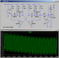
") . When I was playing around something like
. When I was playing around something like