 Facebook
 Google
 GitHub
 Linkedin
Hi,
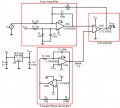
Following this document I built the attached circuit on a breadboard, though I'm using an LM393 and a TL072 and some different component values in the triangle generator. It's not the greatest looking PWM but it works.
What I don't really understand is why unfiltered V_PWM is fed back through R4 to the error amplifier. Wouldn't you much rather first run V_PWM through a filter and feed that filtered signal back to the error amplifier?
Attachments
-
 49.1 KB Views: 26


