Facebook
 Google
 GitHub
 Linkedin
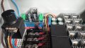
So to be sure I'm getting you correctly. The regulator will feed the relay module which in turn also powers the coil side of the relay? The contact side that I think has its own 12 volt supply that doesn't care what the voltage is (12-14 volts), it's just contacts ?No I believe it is always grounded(I can check again if needed). I think I mentioned in the past if the rotary switch was turned to the detented off or zero one or both A1 and or A2 were grounded to A for some reason but I will need to confirm. I needed to turn the switch on to get the brake to hold and everything to function fine.(With engine off)
Electromagnetic brake
- Thread starter rgsawmill
- Start date