Electromagnetic brake

Thread Starter

rgsawmill

Joined Apr 13, 2025
103
That's an easy one I think. You need to power the relay module from the same 12v supply as the PWM controller, so that when the PWM is powered down so is the relay module.


Hmmm, ok, this is a little trickier but I suspect I know what the issue is. When the battery is charging what is the battery voltage and what is the voltage at the 'in' terminal?
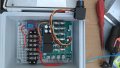
That's an other problem. I will need to put a high amp switch or e-stop button between the battery and the PWM. Right now I am not killing the power to it, I'm turning the potentiometer dial to the detected off and apparently it does not shut down everything.
I did not test the voltage with engine running but I don't think it would be over 14 volts.
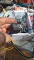
Yes I am powering the relay from a terminal strip that is jumpered to main power into PWM.
 

Attachments

Thread Starter

rgsawmill

Joined Apr 13, 2025
103
That's an easy one I think. You need to power the relay module from the same 12v supply as the PWM controller, so that when the PWM is powered down so is the relay module.


Hmmm, ok, this is a little trickier but I suspect I know what the issue is. When the battery is charging what is the battery voltage and what is the voltage at the 'in' terminal?
I have folded up everything for the evening so I can spend some time with the wife but if you could tell me what tests you would like me to do I will do them in the morning and get back to you. Do you think it is some sort of frequency thing ?
Tks Bob G.
 

Thread Starter

rgsawmill

Joined Apr 13, 2025
103
I have folded up everything for the evening so I can spend some time with the wife but if you could tell me what tests you would like me to do I will do them in the morning and get back to you. Do you think it is some sort of frequency thing ?
Tks Bob G.
I think I forgot to add that when I shut off the engine the brake stayed energized (released) and red activation light on the relay remains on. Eventually the light continues to dim and eventually goes out and stops supplying power to the brake. Then with the engine off I can resume operating the mill controller and manual up down buttons and everything works grate. Allowing the mill controller to actuate the head per programed target locations it stops exactly on target as it should.
So I'm assuming that the PWM grounds the directional control A to A1 and/or A2 when the switch/potentiometer is turned off. That must be why the relay module is activating the brake ckt.
Why when running the engine dose the relay module stay activated and when I shut the engine off dose the power slowly dissipate and eventually set the brake I don't know.
The only difference seems to be the charging ckt.
 

Thread Starter

rgsawmill

Joined Apr 13, 2025
103
I think I forgot to add that when I shut off the engine the brake stayed energized (released) and red activation light on the relay remains on. Eventually the light continues to dim and eventually goes out and stops supplying power to the brake. Then with the engine off I can resume operating the mill controller and manual up down buttons and everything works grate. Allowing the mill controller to actuate the head per programed target locations it stops exactly on target as it should.
So I'm assuming that the PWM grounds the directional control A to A1 and/or A2 when the switch/potentiometer is turned off. That must be why the relay module is activating the brake ckt.
Why when running the engine dose the relay module stay activated and when I shut the engine off dose the power slowly dissipate and eventually set the brake I don't know.
The only difference seems to be the charging ckt.
Good morning sir.
So testing with engine off everything works flawlessly. 12.2 volts at B+ and 0 volts on NO terminal on relay board.
Engine running I have 13.9 volts at B+ and 13.9 on NO terminal which is releasing the brake.
After shutting the engine off the NO terminal remains at 12.5 volts for approx. 3 minutes then dropped to 0 volts and red activation light slowly dimms then goes out.
It's acting like the power is trapped on the coil side of the relay and slowly disipates.
Could it be the 14 volts is somehow to much for the relay ? It's over my Hever
I think I forgot to add that when I shut off the engine the brake stayed energized (released) and red activation light on the relay remains on. Eventually the light continues to dim and eventually goes out and stops supplying power to the brake. Then with the engine off I can resume operating the mill controller and manual up down buttons and everything works grate. Allowing the mill controller to actuate the head per programed target locations it stops exactly on target as it should.
So I'm assuming that the PWM grounds the directional control A to A1 and/or A2 when the switch/potentiometer is turned off. That must be why the relay module is activating the brake ckt.
Why when running the engine dose the relay module stay activated and when I shut the engine off dose the power slowly dissipate and eventually set the brake I don't know.
The only difference seems to be the charging ckt.
Good morning sir
I have tested the setworks again.
Engine off I have 12.1 volts at the relay module B+ and 0 volts on NO terminal.
When moving the head the B+ is 11.1 and NO goes to 10.9 volts. Everything works flawlessly.
Engine running: the B+ goes up to 14 volts and NO terminal goes up to 13.9volts and the brake released and the head begins to drop.
Shet off the engine the NO terminal remains at 13 volts for a few minutes then drops off to 0 volts and red activation light slowly dimms and goes out.
 

Thread Starter

rgsawmill

Joined Apr 13, 2025
103
Good morning sir.
So testing with engine off everything works flawlessly. 12.2 volts at B+ and 0 volts on NO terminal on relay board.
Engine running I have 13.9 volts at B+ and 13.9 on NO terminal which is releasing the brake.
After shutting the engine off the NO terminal remains at 12.5 volts for approx. 3 minutes then dropped to 0 volts and red activation light slowly dimms then goes out.
It's acting like the power is trapped on the coil side of the relay and slowly disipates.
Could it be the 14 volts is somehow to much for the relay ? It's over my Hever

Good morning sir
I have tested the setworks again.
Engine off I have 12.1 volts at the relay module B+ and 0 volts on NO terminal.
When moving the head the B+ is 11.1 and NO goes to 10.9 volts. Everything works flawlessly.
Engine running: the B+ goes up to 14 volts and NO terminal goes up to 13.9volts and the brake released and the head begins to drop.
Shet off the engine the NO terminal remains at 13 volts for a few minutes then drops off to 0 volts and red activation light slowly dimms and goes out.
Does the 14 volts to the relay mess it up somehow ?
 

Irving

Joined Jan 30, 2016
5,123
Yes, the 14v level is affecting to on/off point of the relay module. I think there's an easy fix, but I'll need to try it out... I happen to have one here :rolleyes: Will get back to you ASAP.
 

tonyStewart

Joined May 8, 2012
237
I once had a custom geared servo motor design that need to stop quickly. I used a full bridge instead of relays. So the stop command applied a short across the motor to act as a brake.

Keep in mind L/R= tau so there is a magnetic time constant working on the force , momentum and deacceleration current due to rpm controlled BEMF/ DCR of coil.

This may be done with relays but you need a power resistor to absorb the heat and limit the current with fly back diodes Or snubbers. The relay needs to be derated for this.
 

MisterBill2

Joined Jan 23, 2018
27,522
I once had a custom geared servo motor design that need to stop quickly. I used a full bridge instead of relays. So the stop command applied a short across the motor to act as a brake.

Keep in mind L/R= tau so there is a magnetic time constant working on the force , momentum and deacceleration current due to rpm controlled BEMF/ DCR of coil.

This may be done with relays but you need a power resistor to absorb the heat and limit the current with fly back diodes Or snubbers. The relay needs to be derated for this.
Certainly dynamic braking can be very effective, and exactly as TS states, allof the components involved must be adequate to survive the task.
The one caution I suggest is to understand that dynamic braking effectiveness seldom extends to a complete stop. So the requirement for additional mechanical braking will depend o the application.
 

Thread Starter

rgsawmill

Joined Apr 13, 2025
103
Certainly dynamic braking can be very effective, and exactly as TS states, allof the components involved must be adequate to survive the task.
The one caution I suggest is to understand that dynamic braking effectiveness seldom extends to a complete stop. So the requirement for additional mechanical braking will depend o the application.
Right now the issue I am having seems to be the optocoupler relay. With the engine off and a steady 12.1 volts the performance is flawless and exact. Ith interface between the setworks computer , PWM and brake relay seems to be perfect.
As soon as I start the engine the charging system (14 volts) is thrown into the system the relay for braking does not open the contacts (applying the brake) for about 2-3 min. When the voltage on the excite side of the relay slowly disipates.
 

MisterBill2

Joined Jan 23, 2018
27,522
Depending on the current required by the control system two choices appear right away. First would be a linear regulator for the logic part of the control circuit, based on not having any clue as to what that is or how much power it requires. The other choice would be a filter to remove engine generated noise from the power.
AND now a third idea is to take the logic power connection directly to the battery terminals. That is based on a guess that the battery voltage does not increase with the engine running. That may not be the case, though.
 

Thread Starter

rgsawmill

Joined Apr 13, 2025
103
Depending on the current required by the control system two choices appear right away. First would be a linear regulator for the logic part of the control circuit, based on not having any clue as to what that is or how much power it requires. The other choice would be a filter to remove engine generated noise from the power.
AND now a third idea is to take the logic power connection directly to the battery terminals. That is based on a guess that the battery voltage does not increase with the engine running. That may not be the case, though.
This is the relay that seems to be effected by the voltage variation. The excite side of the relay draws very little amperage.
 

Attachments

MisterBill2

Joined Jan 23, 2018
27,522
The relay module is a lot more complex than just a relay. BUT, if the contacts are totally isolated from the rest of the relay circuit then a simple fix would appear to be powering that module with a three terminal linear 12 volt voltage regulator. My only caution about that is to be sure to provide the 0.1 MFD capacitors for the input and output terminals, as described in the application information. An adequate regulator would be the LM7812. Similar three terminal IC regulators can also work.
 

Irving

Joined Jan 30, 2016
5,123
Good evening sir. Just checking to see if you had a chance it look into my debacle . Sorry to be a pain.
Tks Bob G.
Hi Bob,

OK, I've tested it out and the problem is indeed that when the supply voltage climbs above 13.2v the relay becomes energised. This is an unfortunate side-effect of the relatively simple design of this module. One solution, is, as MB2 said above, a simple linear voltage regulator. Its a bit messy to wire up at the component level though relatively cheap. How are your fine soldering skills? The other option is a ready-made module featuring the same regulator chip, which is only slightly more expensive;

1746286366091.png
https://www.amazon.com/KOOBOOK-Terminal-Regulator-Voltage-Regulated/dp/B07S88BWBM/

Make sure you order the 12v one (they also come in 3.3, 5, and 9v versions). Wire the input side (on left) to the battery (doesn't matter which way round) and the output side on right to the relay module (+ = VCC, - = GND).
 

Thread Starter

rgsawmill

Joined Apr 13, 2025
103
Hi Bob,

OK, I've tested it out and the problem is indeed that when the supply voltage climbs above 13.2v the relay becomes energised. This is an unfortunate side-effect of the relatively simple design of this module. One solution, is, as MB2 said above, a simple linear voltage regulator. Its a bit messy to wire up at the component level though relatively cheap. How are your fine soldering skills? The other option is a ready-made module featuring the same regulator chip, which is only slightly more expensive;

View attachment 348354
https://www.amazon.com/KOOBOOK-Terminal-Regulator-Voltage-Regulated/dp/B07S88BWBM/

Make sure you order the 12v one (they also come in 3.3, 5, and 9v versions). Wire the input side (on left) to the battery (doesn't matter which way round) and the output side on right to the relay module (+ = VCC, - = GND).
Your recommending the 7812 unit ? And I'm assuming that unit dose not require capacitors added?
It also says three terminal. Do you hook up battery + and - on the left side and + and - on right side to the relay module?
 

Thread Starter

rgsawmill

Joined Apr 13, 2025
103
Hi Bob,

OK, I've tested it out and the problem is indeed that when the supply voltage climbs above 13.2v the relay becomes energised. This is an unfortunate side-effect of the relatively simple design of this module. One solution, is, as MB2 said above, a simple linear voltage regulator. Its a bit messy to wire up at the component level though relatively cheap. How are your fine soldering skills? The other option is a ready-made module featuring the same regulator chip, which is only slightly more expensive;

View attachment 348354
https://www.amazon.com/KOOBOOK-Terminal-Regulator-Voltage-Regulated/dp/B07S88BWBM/

Make sure you order the 12v one (they also come in 3.3, 5, and 9v versions). Wire the input side (on left) to the battery (doesn't matter which way round) and the output side on right to the relay module (+ = VCC, - = GND).
I have been able to do fine soldering in the past. However witch one requires no soldering ?
 

Thread Starter

rgsawmill

Joined Apr 13, 2025
103
Your recommending the 7812 unit ? And I'm assuming that unit dose not require capacitors added?
It also says three terminal. Do you hook up battery + and - on the left side and + and - on right side to the relay module?
I have wired in a what I feel a not sensitive relay and the same situation occurred. The ground side of the winding goes to A1 and A2 via two blocking diods . When selecting up or down A1or A2 is directed to ground terminal A through the PWM. When stoping an up or down command the connection between A1 or A2 is closed losing the ground. However A1 and A2 still have 11.4 volts with no place to go. Even though there are blocking diods between A1 and A2 and the ground side of the relay the 11.7 volts are trapped not allowing the relay contacts to open. 13.6 on hot side of relay winding.
Do all 12 volts relays have a problem when the voltage gets to around 13.6 volts ?
 

Attachments

Thread Starter

rgsawmill

Joined Apr 13, 2025
103
I have wired in a what I feel a not sensitive relay and the same situation occurred. The ground side of the winding goes to A1 and A2 via two blocking diods . When selecting up or down A1or A2 is directed to ground terminal A through the PWM. When stoping an up or down command the connection between A1 or A2 is closed losing the ground. However A1 and A2 still have 11.4 volts with no place to go. Even though there are blocking diods between A1 and A2 and the ground side of the relay the 11.7 volts are trapped not allowing the relay contacts to open. 13.6 on hot side of relay winding.
Do all 12 volts relays have a problem when the voltage gets to around 13.6 volts ?
Sorry to everyone for what I'm sure you feel are dumb questions but I guess I don't know what I don't know. In the many years of working on equipment I guess I've never come across this. Thank you all for your help.
 

Irving

Joined Jan 30, 2016
5,123
I have been able to do fine soldering in the past. However witch one requires no soldering ?
The module I suggested in post #95 is ready to go and needs no soldering, just wiring up.

If you want to solder something together you need the following:

LM7812 voltage regulator in a TO-220 case
1 x 0.1uF ceramic capacitor
1 x 0.33uF ceramic capacitor
1 x 1N400x diode

Wired like this:

7812.png
 
Last edited:
Top