Electromagnetic Pendulum (pulse movement) (2)

Thread Starter

kicksnj

Joined Mar 20, 2025
10
Here's the one I made for my wooden clock.
View attachment 154059
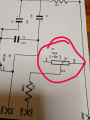
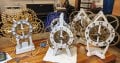
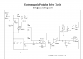
Would you have a parts list for this? I'm into pendulum clock building. I understand most of the schematic.
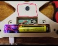
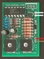
I've been using the cheap pendulum drivers on AliExpress but they are just not reliable. But a few of the parts I'm not sure what to order. Any help for this new hobbyist would be appreciated. Thank you.

Moderator edit : New thread created from this.
 

panic mode

Joined Oct 10, 2011
4,864
what parts you need help with? all parts have values and this is low voltage, low power circuit so any resistor or capacitor of suitable value will do.
 

Thread Starter

kicksnj

Joined Mar 20, 2025
10
what parts you need help with? all parts have values and this is low voltage, low power circuit so any resistor or capacitor of suitable value will do.
Hi thank you for your help. Sorry, I'm in my 70's and my mind is not what it used to be lol .. the one I'm not sure if is P1 500R. I'm assuming it's a pot switch? Here's a picture of what I'm making.
 

Attachments

Last edited:

panic mode

Joined Oct 10, 2011
4,864
correct, C3 is not polarized so it can be connected either way. it is a very common 100nF or 0.1uF capacitor.

4.7uF and 10uF are reasonably low value so if you like C1 and C3 could also be selected as nonpolarized variants (something like C322C106K3R5TA)
 
Last edited:

Thread Starter

kicksnj

Joined Mar 20, 2025
10
correct, C3 is not polarized so it can be connected either way. it is a very common 100nF or 0.1uF capacitor.

4.7uF and 10uF are reasonably low value so if you like C1 and C3 could also be selected as nonpolarized variants (something like C322C106K3R5TA)
Ok... Thanks so much for your help. I'm going to order all the parts and keep my figures crossed lol... I actually ordered someone else's board I saw today. But it's on the expensive side to buy several of them. I make a lot of the clocks for family and friends. So if I can make the board myself I would rather do that. The only reason I ordered this guy's board is there looks like a lot more to it 1, and it has a gain and pulse pot on it to maybe zero in on time more accurately. His board was $50
 

Attachments

panic mode

Joined Oct 10, 2011
4,864
Ouch...

All the resistors and trimpts are cheap carbon type so they drift with temperature like crazy. That looks like a $3-4 product. i would say $10-15 is reasonable, $20 is tolerable and $50 is a robbery...

lets see, PCB is $0.50, cannot really see but IC is probably justy quad opamp (MPC6044 or whatever) so maybe $1.50, and remaining parts are maybe $2-3... i would say my estimate stands.
 
Last edited:

Thread Starter

kicksnj

Joined Mar 20, 2025
10
Ouch...

All the resistors and trimpts are cheap carbon type so they drift with temperature like crazy. That looks like a $3-4 product. i would say $10-15 is reasonable, $20 is tolerable and $50 is a robbery...

lets see, PCB is $0.50, cannot really see but IC is probably justy quad opamp (MPC6044 or whatever) so maybe $1.50, and remaining parts are maybe $2-3... i would say my estimate stands.
It is a 6044. And what's even more strange is that I didn't know he had the schematic up on his website. What's strange is the schematic is showing 4 6044 chips not just 1 like the photo of the board I showed you. So now I'm wondering what am I getting for $50 lol..... I'll post a picture when I get it. But I think your right. I got taken.
 

Thread Starter

kicksnj

Joined Mar 20, 2025
10
Ouch...

All the resistors and trimpts are cheap carbon type so they drift with temperature like crazy. That looks like a $3-4 product. i would say $10-15 is reasonable, $20 is tolerable and $50 is a robbery...

lets see, PCB is $0.50, cannot really see but IC is probably justy quad opamp (MPC6044 or whatever) so maybe $1.50, and remaining parts are maybe $2-3... i would say my estimate stands.
It is a 6044. And what's even more strange is that I didn't know he had the schematic up on his website. What's strange is the schematic is showing 4 6044 chips not just 1 like the photo of the board I showed you. So now I'm wondering what am I getting for $50 lol.....
 

Attachments

panic mode

Joined Oct 10, 2011
4,864
looks like $50 will get you 100 boards ($17.90 for boards + $31 for shipping).
this was done in 15min in KiCad 8. entire project is included and newer version should open it as well.
inside "production folder is a another ZIP file with gerber files. just drop it on JLC website and manipulate quantity etc to see something that fits the budget (for $25 you get 20 boards). granted those are just PCBs without parts. you still need parts.

1742506187754.png

1742506234357.png

1742506256993.png
 

Attachments

Thread Starter

kicksnj

Joined Mar 20, 2025
10
looks like $50 will get you 100 boards ($17.90 for boards + $31 for shipping).
this was done in 15min in KiCad 8. entire project is included and newer version should open it as well.
inside "production folder is a another ZIP file with gerber files. just drop it on JLC website and manipulate quantity etc to see something that fits the budget (for $25 you get 20 boards). granted those are just PCBs without parts. you still need parts.

View attachment 345035

View attachment 345036

View attachment 345037
omg.... I don't know what to say. thank you sooo much. if this really gets me closer then those cheap pendulum drivers I would be more than happy to send you a clock :)
 

panic mode

Joined Oct 10, 2011
4,864
Oh yeah..?
what about this one:
1742516064850.png

i marked Q1, J1 R1 and R8 as "do not populate" so that one can take advantage of cheaper assembly. Then most of the parts would be assembled at the factory. So what you would receive would look like next image. And those last few parts are through hole so you can easily solder them yourself.

1742516034515.png

right now website is giving me some trouble so will need to try a bit later but it goes something like this:

suppose you are getting 20 boards (min quantity is 5) so that is some $7 i think, and want them populated as shown above (Economic assembly), then all parts for those 20 boards would cost some $25, plus $6 for the Extended parts ($3 per part type), plus some $25-30 for shipping. the $3 per extended part is because Extended parts are not at hand - someone need to walk through the warehouse and find them, then load them into machine. if you order bigger batch of boards, the cost of extended part get diluted when you look at cost per board.

1742516924374.png
 

Thread Starter

kicksnj

Joined Mar 20, 2025
10
Oh yeah..?
what about this one:
View attachment 345062

i marked Q1, J1 R1 and R8 as "do not populate" so that one can take advantage of cheaper assembly. Then most of the parts would be assembled at the factory. So what you would receive would look like next image. And those last few parts are through hole so you can easily solder them yourself.

View attachment 345061

right now website is giving me some trouble so will need to try a bit later but it goes something like this:

suppose you are getting 20 boards (min quantity is 5) so that is some $7 i think, and want them populated as shown above (Economic assembly), then all parts for those 20 boards would cost some $25, plus $6 for the Extended parts ($3 per part type), plus some $25-30 for shipping. the $3 per extended part is because Extended parts are not at hand - someone need to walk through the warehouse and find them, then load them into machine. if you order bigger batch of boards, the cost of extended part get diluted when you look at cost per board.

View attachment 345065
Omg you are too much . That is fantastic. But let me first get this guy's board that I paid $50 for and see if it will even work. I might have to redesign the clock base to be sure I have space for the PCB and battery. I'm using 1 18650 lithium ion battery work a rechargeable board. So the clock will run by USB-C 5v little charger as well as recharge the battery at the same time. Or you can pull out the cord and the clock will run off the 18650 battery for about 6 to 8 months before charging.
 

panic mode

Joined Oct 10, 2011
4,864
no worries... i was just playing with things and decided to use this as an example and learning opportunity for anyone interested in prototyping, or PCBA (assembly services).

since most of the parts nowadays are SMD (and they are smaller and cheaper) it makes sense to use them. but assembly services are not expensive.... and prices for parts that PCBA houses charge are lower than ordering from Mouser, DigiKey etc.

if ordering PCB only for designs that use SMD parts, one can solder the parts by hand but any time volume is involved, it is better to order stencil and do soldering in reflow oven (even if DIY one).

for prototypes i usually order either just PCB or partially assembled boards.
either way one need to pay attention to board, silkscreen etc. to ensure that received files match expectations.
if ordering boards with assembly service, it is important to check things like part placement, orientation etc.

in this project i used standard SOIC footprint as included with KiCad. normally i would use one from my own library that i modified, so when submitting BOM and placement files, one is presented with view like in the next image but...the IC is rotated 90deg. in some instances parts may be shifted and rotated.

but... do not panic, this is easy to fix even without resubmitting modified design. just click on the part and move it/rotate it until it is shown correctly... and in case of shift, it does not need to be very precise, they will correct it themselves...

so for anyone trying to practice, have at it, files are here and U1 correct orientation is like shown here (pin1 is in upper left corner, next to the longer silkscreen line.
1742521238031.png

one need to be careful about all polarized parts (diodes, alu capacitors, etc.).
so for testing or small batch of proto boards, manual corrections are ok, but in the long run you want to avoid mistakes - hence the reason for own libraries.

Economic assembly has some restrictions:
parts can only be assembled on one side of the board (either top or bottom).
only surface mount parts can be used,
only single temperature setting is used. so delicate parts may get deformed,
etc.

Standard assembly allows parts on both sides of the board, as well as through hole parts. one can specify reflow temp etc.

i also included original schematics for those who want to compare it to what i did
1742521660564.png

i like to declare other fields so that is another reason for own libraries. for example chosen components have very long part numbers. those need to be entered in the Value field, but i would rather have something shorter for value to reduce clutter on the schematics. so i simply create another field Value2 that has shorter info. Same is for LCSC or JLC part numbers.

1742521986553.png

parts that you do not want assblmed need to be marked as "do not populate". then they appear with red X in schematics.
mounting holes, solder jumpers etc are features on the PCB. they do not need to be in the BOM. KiCad 9.x has libraries that have this corrected (could have been done sooner).
1742522416579.png
 

Attachments

Thread Starter

kicksnj

Joined Mar 20, 2025
10
no worries... i was just playing with things and decided to use this as an example and learning opportunity for anyone interested in prototyping, or PCBA (assembly services).

since most of the parts nowadays are SMD (and they are smaller and cheaper) it makes sense to use them. but assembly services are not expensive.... and prices for parts that PCBA houses charge are lower than ordering from Mouser, DigiKey etc.

if ordering PCB only for designs that use SMD parts, one can solder the parts by hand but any time volume is involved, it is better to order stencil and do soldering in reflow oven (even if DIY one).

for prototypes i usually order either just PCB or partially assembled boards.
either way one need to pay attention to board, silkscreen etc. to ensure that received files match expectations.
if ordering boards with assembly service, it is important to check things like part placement, orientation etc.

in this project i used standard SOIC footprint as included with KiCad. normally i would use one from my own library that i modified, so when submitting BOM and placement files, one is presented with view like in the next image but...the IC is rotated 90deg. in some instances parts may be shifted and rotated.

but... do not panic, this is easy to fix even without resubmitting modified design. just click on the part and move it/rotate it until it is shown correctly... and in case of shift, it does not need to be very precise, they will correct it themselves...

so for anyone trying to practice, have at it, files are here and U1 correct orientation is like shown here (pin1 is in upper left corner, next to the longer silkscreen line.
View attachment 345071

one need to be careful about all polarized parts (diodes, alu capacitors, etc.).
so for testing or small batch of proto boards, manual corrections are ok, but in the long run you want to avoid mistakes - hence the reason for own libraries.

Economic assembly has some restrictions:
parts can only be assembled on one side of the board (either top or bottom).
only surface mount parts can be used,
only single temperature setting is used. so delicate parts may get deformed,
etc.

Standard assembly allows parts on both sides of the board, as well as through hole parts. one can specify reflow temp etc.

i also included original schematics for those who want to compare it to what i did
View attachment 345073

i like to declare other fields so that is another reason for own libraries. for example chosen components have very long part numbers. those need to be entered in the Value field, but i would rather have something shorter for value to reduce clutter on the schematics. so i simply create another field Value2 that has shorter info. Same is for LCSC or JLC part numbers.

View attachment 345076

parts that you do not want assblmed need to be marked as "do not populate". then they appear with red X in schematics.
mounting holes, solder jumpers etc are features on the PCB. they do not need to be in the BOM. KiCad 9.x has libraries that have this corrected (could have been done sooner).
View attachment 345079
This is what I am working with as far as the base space. I still have some wiggle room in front of the coil. Of course the cheap PCB would be pulled out. And red circle can expand the base more. I'm printing a test base to see what space I will have. It's going to take 6 hours to print. Or redesign the base to be a rectangular box.
 

Attachments

Thread Starter

kicksnj

Joined Mar 20, 2025
10
This is what I am working with as far as the base space. I still have some wiggle room in front of the coil. Of course the cheap PCB would be pulled out. And red circle can expand the base more. I'm printing a test base to see what space I will have. It's going to take 6 hours to print. Or redesign the base to be a rectangular box.
Good morning. I have another very interesting schematic that I didn't see on Dick's website. It's a "regulated pendulum driver". What was very interesting was in the way you set the time. Instead of turning pots you physically adjust the Bob on the pendulum arm up and down like I've been doing with this cheap pendulum driver from AliExpress. What's unique with this version of the board is that he has an LED light that turns green or red determines it's a pendulum is swinging too fast or too slow. And until the LED light goes out completely you are then targeted at the proper tolerance for the board to keep proper time. The only concern was it sounds like he programmed one of the chips. Which of course I would not have a code for. But I've attached the PDF file. He talks about setting the LED on the next to the last page before the schematic. Does this look like something that would have to be programmed or is he just saying that. And again I mean it you have a clock of your choice coming to you for all the help you are giving me .:)Screenshot 2025-03-21 083424.png
 

Attachments

Seaskiff

Joined Aug 1, 2025
3
Good morning. I have another very interesting schematic that I didn't see on Dick's website. It's a "regulated pendulum driver". What was very interesting was in the way you set the time. Instead of turning pots you physically adjust the Bob on the pendulum arm up and down like I've been doing with this cheap pendulum driver from AliExpress. What's unique with this version of the board is that he has an LED light that turns green or red determines it's a pendulum is swinging too fast or too slow. And until the LED light goes out completely you are then targeted at the proper tolerance for the board to keep proper time. The only concern was it sounds like he programmed one of the chips. Which of course I would not have a code for. But I've attached the PDF file. He talks about setting the LED on the next to the last page before the schematic. Does this look like something that would have to be programmed or is he just saying that. And again I mean it you have a clock of your choice coming to you for all the help you are giving me .:)View attachment 345107
I have been following your posts, and am curious how you ended up with your pursuit. I too build wooden clocks and have found interest in incorporating an electromagnetic drive circuit.
 
Top