Electromagnetic brake

Thread Starter

rgsawmill

Joined Apr 13, 2025
103
Good afternoon all,
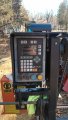
I am attempting to add a system to raise and lower the saw head on my manual mill. I have added a setworks computer that has the capability of activating a motor to bring the blade to preprogrammed locations to make a cut.
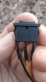
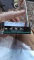
I have acquired a wheelchair motor with a gearbox and electromagnetic brake attached, a PWM with a switch for reversing polarity through the PWM and a pot for motor speed control.
My issue is I don't think the gear reduction is enough resistance to hold the weight of the saw head so I would like to use the electromagnetic brake on the back of the motor.
I will need the motor to stop and hold the load fairly instantaneously when the PWM stops supplying power to the motor or I am afraid the setworks controller may hunt to set the head at the programed location.
The brake is in my mind just a winding that draws .2 amps load when activated with 12 volts.
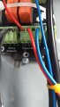
Can I supply voltage to the brake winding from the M1 and M2 wires with blocking diods to prevent electrical flow between M1+M2 so the brake will release when activating the motor in either direction ?
Will the brake apply instantaneously or will there be enough voltage remaining in M1+M2 after the PWM relay contacts open to creat a lag in brake application causing the head to move off of location ?
Hopefully I am explaining myself clearly enough.
Tks Bob G.
 
Last edited:

LowQCab

Joined Nov 6, 2012
5,101
If it has "an Electro-Magnetic-Brake attached",
then there are no Electrical Connections to the Motor-Windings,
when used in the original application. and may be treated as a separate device.

In order for the "Setworks-Computer" to know where the "Pre-Programmed-Location" is
there must be some kind of Linear-Position-Sensor, or Rotary-Position-Sensor, installed.
Is this Sensor installed ?, or
is this Sensor an integral part of the proper Motor specified by "Setworks-Computer" ?

Does the "Setworks-Computer" have a "Brake-Output" for the axis that You are working with ?,
or does it manipulate the Motor-Output in such a way to cause the Motor to "lock-up" ?,
( such as applying a small AC-Voltage to the Motor ? )

What type of Motor is the "Setworks-Computer" designed to operate ?
Where is the PDF-Spec-Sheet for this specified type of Motor ?

Guessing usually doesn't work very well.
.
.
.
 

Thread Starter

rgsawmill

Joined Apr 13, 2025
103
Thank you for your response.
The motor I have has no labeling or specs on it as I am seeing from other people trying to use them in other projects.
My setworks dose have a linear encoder that I have mounted and the setworks is functional and very accurate . However I am operating in a manual mode at this time and am manually raising and lowering the saw head to the computers target elevation.
If I switch it to auto mode it will activate a relay board (8 amp) that will open and close contacts depending on desired direction of travel. This ckt is designed to activate a PWM or motor control relays only. Not capable of carrying the load to drive a motor.
The relay out terminals on the setworks are #1#2#3#4.
The polarity control switch on the PWM are A1,A,A2. These excite the relays to switch polarity or shut it off.
In testing A is a common ground that completes the ckt between A1-a / A2-A or center is open. So it seems to supply a ground to excite the relays in the PWM to change motor direction.
So wiring the setworks relays out terminals I will have to bridge #2+3 to A, #1 to A1, #4 to A2 to control polarity for motor rotation/direction.
From the PWM I will just run the two motor out M1+M2 to the motor.
Now I have to deal with the brake. This is where I am unclear where the proper location is to get the supply voltage to release the brake and take away voltage to apply the brake as quickly as possible to 1) eliminate the possibilities of motor slippage 2) eliminate internal wear for longevity .
If I supply the brake winding from M1+M2 through blocking diods will it perform instantaneously or will there some kind of residual power that will cause the brake sluggish?
The setworks is a Mikron SW-350 pro made by LYTUS in Lithuania.
They will not supply me with schematics however I think I have the control ckt. Between that and the PWM figured out. It's the brake actuation that I am concerned about now.
 

Attachments

Last edited:

LowQCab

Joined Nov 6, 2012
5,101
OK, so You can't get a Schematic.
With Outputs consisting only of "Relay-Contacts", a Schematic is not necessary.

But an illustrated-Instruction-Manual is an absolute necessity.

And, how do You KNOW that the Outputs are merely Relay-Contacts ?


A million words of your "guesses" and "assumptions" about what does what,
does not convey enough understanding for anyone here to make a
solid, reliable, suggestion on the best way to proceed.

You may need to purchase a specific, dedicated, Motor from Setworks-Company.

Do You have working Motors on the other axes of the Machine ?

Where did the other Motors that are working come from ?, are they supplied by Setworks ?

Do the other Motors that You already have installed and working operate with varying speeds ?

Do the other Motors that You already have installed and working operate with an external Brake ?


If You can't get answers to ALL of the above questions,
it is very unlikely that You will end-up-with a satisfactorily operating Machine.
.
.
.
 

Thread Starter

rgsawmill

Joined Apr 13, 2025
103
I agree with your reply .
I have contacted the setworks manufacturer and have struggled with the language barrier to some extent. They have no recommendations other than to say that other users of there system have used hoist motors and gear motors that have enough mechanical advantage to hold the load.
I asked them for schematics because I am fairly familiar with reading them . As I said they were not willing to send them to me. During my questioning I did get the information about the relays stating that the outputs are only the contact side of the relays and no voltages are present. I'm sure if needed a voltage could be introduced if needed however to control my PWM all I need is intermittent continuity to control the ground side of those relays.
I have no automation on the mill at this time except the setworks that at this point is a DRO of blade location with the ability to calculate a cut list , deduct saw kerf and indicate a target for the next cut.
I wish to at this time to add a powered saw head that will automatically locate each cut.
I understand your frustration as I am feeling the same.
If the setworks manufacturer had a material list of recommended components I would have bought them by now .
I will continue with my research and fabrication of a system that I can mount to my mill with minimal modification so it can be returned to original if my components do not perform satisfactorily. Unfortunately as you I have a lot of unanswered questions that I will have to answer by trial and hopefully no error.
Thank you for your time.
 

LowQCab

Joined Nov 6, 2012
5,101
Ask the manufacturer for a PDF Instruction-Manual.
They can simply Email it to You, and then You can post a copy of it here.

A manual-Speed-Control-Knob may be required.
,
,
,
 

Tonyr1084

Joined Sep 24, 2015
9,744
Welcome to AAC.

Question about the drive: Is the motor and gear reduction a "Worm Gear"? If so then stopping the motor at the desired location should stop and hold the cutter head where you want it. Otherwise if it is a chain of gear reduction then the head could move. But generally if you hold the motor leads shorted AND if the motor has a permanent magnet then the motor will resist movement. With the chain of gears the slightest movement would spin the motor but being shorted it will resist movement. You MIGHT get some movement over a longer period of time - but I couldn't say what that would be.

My kids had ride on toys that were worm chain of gear drive. When they took their foot off the brake pedal (counter-intuitive) power to the motor would be cut and its leads would be shorted. The drive wheels would practically lock up. But I HAVE seen the wheels turn even with the motor shorted. So if yours is worm drive then braking should be no problem.
 

Thread Starter

rgsawmill

Joined Apr 13, 2025
103
Ask the manufacturer for a PDF Instruction-Manual.
They can simply Email it to You, and then You can post a copy of it here.

A manual-Speed-Control-Knob may be required.
,
,
,
Thank you for your response.
I have not opened the gear box up but I do believe it is a worm gear drive with an other set if in line gears that allows one of them to slide manually so you can disengage the motor in an emergency.
The motor is equiped with an electronic brake that must have a friction disc that is clamped when no voltage is applied. (.2 amps load).
With the brake removed or energized with 12 volts I can spin the shaft with a 6" wrench by hand. With the brake applied o can not spin the output shaft.
It is a permanent magnet brushed motor.
I have bench tested the motor with the PWM for function but with the brake removed.
The brake is a simple winding with a power and ground wire (I don't think polarity matters).
The motor has two leads that polarity will be controlled by the PWM along with speed.
My question is: will the brake apply and release instantaneously if I supply voltage via the M1+M2 leads going to the motor along with two diods to prevent back feeding. The other brake winding lead will go directly to B- on the PWM.
From what I have been reading a motor will generate power and may interfere with the application of brake . Or am I reading to much into this . I am not an electrician as I'm sure you have noticed however I have been a mobile heavy lift (crane) and heavy equipment mechanic for 30+ years, so I'm not completely ignorant.
The motor and motor control will be powered with 12 volts DC.
Tks Bob G
 

Thread Starter

rgsawmill

Joined Apr 13, 2025
103
Welcome to AAC.

Question about the drive: Is the motor and gear reduction a "Worm Gear"? If so then stopping the motor at the desired location should stop and hold the cutter head where you want it. Otherwise if it is a chain of gear reduction then the head could move. But generally if you hold the motor leads shorted AND if the motor has a permanent magnet then the motor will resist movement. With the chain of gears the slightest movement would spin the motor but being shorted it will resist movement. You MIGHT get some movement over a longer period of time - but I couldn't say what that would be.

My kids had ride on toys that were worm chain of gear drive. When they took their foot off the brake pedal (counter-intuitive) power to the motor would be cut and its leads would be shorted. The drive wheels would practically lock up. But I HAVE seen the wheels turn even with the motor shorted. So if yours is worm drive then braking should be no problem.
KIMG0108.JPGKIMG0157.JPGKIMG9899.JPGKIMG9901.JPGKIMG0108.JPGKIMG0157.JPGKIMG9899.JPGKIMG9901.JPG
 

Thread Starter

rgsawmill

Joined Apr 13, 2025
103
Welcome to AAC.

Question about the drive: Is the motor and gear reduction a "Worm Gear"? If so then stopping the motor at the desired location should stop and hold the cutter head where you want it. Otherwise if it is a chain of gear reduction then the head could move. But generally if you hold the motor leads shorted AND if the motor has a permanent magnet then the motor will resist movement. With the chain of gears the slightest movement would spin the motor but being shorted it will resist movement. You MIGHT get some movement over a longer period of time - but I couldn't say what that would be.

My kids had ride on toys that were worm chain of gear drive. When they took their foot off the brake pedal (counter-intuitive) power to the motor would be cut and its leads would be shorted. The drive wheels would practically lock up. But I HAVE seen the wheels turn even with the motor shorted. So if yours is worm drive then braking should be no problem.
Sorry I think I responded in text to your post in someone else's response.
 

Tonyr1084

Joined Sep 24, 2015
9,744
Then it would be my guess that the brake automatically engages when the motor is unpowered. If you're able to turn the gears with no power applied then the brake is defective. But that's a "Guess".
 

Thread Starter

rgsawmill

Joined Apr 13, 2025
103
Found this:
Looks a lot like the one you have.
Did you see my text I sent to lowQcab by mistake? As well as the photos ? What do you think about energizing the brake ? Any of my drawn schematics look like they will work with some precision not allowing the gear motor to creep ?
 

Thread Starter

rgsawmill

Joined Apr 13, 2025
103
Then it would be my guess that the brake automatically engages when the motor is unpowered. If you're able to turn the gears with no power applied then the brake is defective. But that's a "Guess".
Yes, with the brake d-energized I can not turn the shaft. I also will be removing the wheel and hub and replacing them with a 10 tooth sprocket.
 

Thread Starter

rgsawmill

Joined Apr 13, 2025
103
Yes, with the brake d-energized I can not turn the shaft. I also will be removing the wheel and hub and replacing them with a 10 tooth sprocket.
The two motor leads and the two brake leads are separated in the receptical which leads me to believe they are controlled independently by the wheelchair controller that I am eliminating. That's why I am trying to operate the brake in parallel with the motor leads in forward and reverse .
 

Tonyr1084

Joined Sep 24, 2015
9,744
Assuming motor speed is controlled via PWM - what is the effective voltage going to the motor at the lowest speed and at full speed? You might be able to use a relay with the coil across the motor input. But that might result in buzzing at very low speeds. The relay can then switch full power to the brakes to release it. An alternative to a relay would be a solid state relay. One that can operate on voltages as low as 5V and as high as 40V. (just poking a number out there for reference)

Since I'm not versed in wheelchairs and jazzies per se' I can only guess, but I think you would not want the wheelchair stopping abruptly. This would be uncomfortable and possibly dangerous to the person riding the scooter. HOWEVER, since you're planning on using this to position a cutting head - abrupt stopping shouldn't be an issue. If timing of the brakes becomes an issue you can always directly post about that here. There are a lot of sharp people here.
 

Thread Starter

rgsawmill

Joined Apr 13, 2025
103
Yes, with the brake d-energized I can not turn the shaft. I also will be removing the wheel and hub and replacing them with a 10 tooth sprocket.
The two motor leads and the two brake leads are separated in the receptical which leads me to believe they are controlled independently by the wheelchair controller that I am eliminating. That's why I am trying to operate the brake in parallel with the motor leads in forward and reverse
Assuming motor speed is controlled via PWM - what is the effective voltage going to the motor at the lowest speed and at full speed? You might be able to use a relay with the coil across the motor input. But that might result in buzzing at very low speeds. The relay can then switch full power to the brakes to release it. An alternative to a relay would be a solid state relay. One that can operate on voltages as low as 5V and as high as 40V. (just poking a number out there for reference)

Since I'm not versed in wheelchairs and jazzies per se' I can only guess, but I think you would not want the wheelchair stopping abruptly. This would be uncomfortable and possibly dangerous to the person riding the scooter. HOWEVER, since you're planning on using this to position a cutting head - abrupt stopping shouldn't be an issue. If timing of the brakes becomes an issue you can always directly post about that here. There are a lot of sharp people here.
Thank you for your insight. With your information I will proceed with my project.
 

Tonyr1084

Joined Sep 24, 2015
9,744
The two motor leads and the two brake leads are separated in the receptical which leads me to believe they are controlled independently by the wheelchair controller that I am eliminating. That's why I am trying to operate the brake in parallel with the motor leads in forward and reverse

Thank you for your insight. With your information I will proceed with my project.
Don't just take my word for it - I'm involved in severe guesswork. Whatever direction you decide upon has to be one of your own decision. I do not want to be responsible for any damage or injury caused by something I said. Take care and proceed with safety in mind above all. Safety for you AND for anyone else who may use something you've designed and built.
 
Top