Facebook
 Google
 GitHub
 Linkedin
panic mode
- Joined Oct 10, 2011
- 5,124
as i was the one designing PCBs for them, i heard some of the feedback. basically:
version with OpAmps was working fine but calibrating correct pendulum length was time consuming.
version with MCU was much simpler to setup but it was sort of finicky with respect to choice of coil and supply voltage.
not sure about long term tests though i would expect MCU version to be more stable due to crystal oscillator.
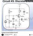
i would also like to point out to an issue with the coil driver circuit. in original circuit as shown in post #17 has Q1 and Q2 connected directly - without any current limiting. if you go that route, i would suggest making some changes. at the very least add a resistor between the transistors:

version with OpAmps was working fine but calibrating correct pendulum length was time consuming.
version with MCU was much simpler to setup but it was sort of finicky with respect to choice of coil and supply voltage.
not sure about long term tests though i would expect MCU version to be more stable due to crystal oscillator.
i would also like to point out to an issue with the coil driver circuit. in original circuit as shown in post #17 has Q1 and Q2 connected directly - without any current limiting. if you go that route, i would suggest making some changes. at the very least add a resistor between the transistors: