Sorry, something I relied to much in the spell suggestion. What I meant is irfz44n.
Question: does microchip makes the picaxe mcu's?
The reason I ask is because I have an old microchip programmer called "PICKit 1" it only program 8 or 14 pins Flash base PIC mcu's.
They do but the Picaxe chips have been preprogrammed with the Picaxe bootstrap firmware code so won't work with the PICKIT1.
The 08M2 is actually a 12F1840.
OK then for your benefit.
On power up all outputs are Low and all variables are set at 0
The output of the TSOP1738 is normally High when not receiving an IR signal.
The first press on the remote sends a series of pulses. First Low side of a pulse sets output 1 (leg 6) High turning on the mosfet.
Pause 1000 gives a 1 second delay for plenty of time to release the button on the remote before the code proceeds to line 5
B0 = 1 provides the logic needed so the next press sets output 1 Low without any delay.
Thank you for the explanation... Which mosfet would you recommend, no just for this instance but also thinking in one that could be versatile in different projects. I ask cause usually it's advantageous to order more than one single unit, probably like 10 units. Just thinking ahead in what else they can be use.
I Thank you and everyone that commented in finding a good option for solving this project.
Here is a simple version using the 4017 without the 555, but it is a bit of a kludge.
The receiver must be able to sink 5mA.
The 4017 has to see a logic low at the clock enable pin.
Notice the receiver output is connected to the clock enable pin not the clock, and the clock is connected to VDD. (+5 volts)
I also noticed the 555-4017 schematic that sghioto posted does not have a power on reset network, so I also omitted it in my circuit, if the 4017 starts outside of the working range you just have to push the remote button until the 4017 comes around to the correct range, if you think that would be a problem I can show the circuit with the POR included. (you only have to bring it around once as long as the power is not removed)
If you have a 4017 laying around this might be worth a try.
I'm the wrong person to ask about a go to logic level NMOS I mostly use standard ones in my projects or load drivers and gate drivers.
I connected that circuit and it does work but when the button is released it's a coin toss as to which state the output of the 4017
will stay in either 0 or 1.
The 555 circuit with the 4017 works perfectly fine even without the power ON reset.
Here is a simple version using the 4017 without the 555, but it is a bit of a kludge.
The receiver must be able to sink 5mA.
The 4017 has to see a logic low at the clock enable pin.
Notice the receiver output is connected to the clock enable pin not the clock, and the clock is connected to VDD. (+5 volts)
I also noticed the 555-4017 schematic that sghioto posted does not have a power on reset network, so I also omitted it in my circuit, if the 4017 starts outside of the working range you just have to push the remote button until the 4017 comes around to the correct range, if you think that would be a problem I can show the circuit with the POR included. (you only have to bring it around once as long as the power is not removed)
If you have a 4017 laying around this might be worth a try.
Well dear friends, I think finally I found a simple solution to my project.
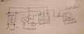
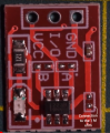
In my continued search, yesterday I found the right combination of simple and inexpensive components. All 3 components I already had, so it was a matter of put them together and test them.
The ON and OFF switching works great with the IR receiver and the touch too.
Now the only problem I have, is how I do calculate the resistor value in order to drive the mosfet..
If you could give a hand, I would appreciate it. The last calculation.
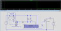
I apologize for the not so up to standard circuit drawing, but it is clear to understand.
Please let me know what you think of and please help me with the resistor calculation.
Thank you...
Hold on here a touch sensor. Where did that come from? Nice! You don't need a gate resistor connect directly to the output of the TTP223. Not sure if you will have enough gate voltage to fully turn on the mosfet but give it a try. That's a IRFZ44N correct?
Hold on here a touch sensor. Where did that come from? Nice! You don't need a gate resistor connect directly to the output of the TTP223. Not sure if you will have enough gate voltage to fully turn on the mosfet but give it a try. That's a IRFZ44N correct?
Well, I found a video showing the circuit, it was in a language I couldn't recognize, I just follow the process easy enough to understand.
Buy itself the circuit works good, but once I connected to the load, it becomes unstable. I thought my choice of the gate resistor was wrong, I tried with 100, 200, 1000 ohm did not work. Once I read you comments that I do not need a resistor, tried, still was not stable. It starts ok, after 30 or 40 seconds, it turns itself off and back again on after 15 seconds or so.
I tried with bjt, 2n222a, same results, with or without the resistor on it's base.
I checked the 5v dc dc power supply, it's stable it's a mini 360 module. Checked for any bad connection's, could not find any. Because the video I saw they use a 3.7v battery to power the circuit, I lower it to 4.5v from the 5.1 v I was feeding it.
Anyway I am at a lost. Don't know what could be wrong. Any thoughts?
I just did check, it's stable. It holds very good. This time around, it did stay on for 3 minutes strait, I thought it might be ok now,, so I turned off touching it, but it didn't respond, so I used the remote and that did turn it off. I waited for a couple minutes and turned on with the remote, waited for another couple minutes then tried to turn it off with the remote, it didn't respond. So I tried with the touch, had to repeatedly try it, still not work, then started to turn off and on again after few seconds.
Any suggestions?
Well, I bypass the resistor, once I power it on, it didn't come on. Checked power to the ttp223 module, it gets the 4.7v ( I cranked up a little just in case). Voltage hold steady but no signs of live there. Checked with touch and remote, nothing. It supposed to do that?
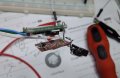
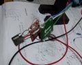
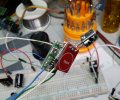
If you removed the 1M resistor the IR sensor is effectively disconnected but the touch sensor should still work. Did you short something out on the touch sensor. Can I see a photo of the actual setup?
If you removed the 1M resistor the IR sensor is effectively disconnected but the touch sensor should still work. Did you short something out on the touch sensor. Can I see a photo of the actual setup?
In the first and last photo I see the output from the IR sensor connected directly to the touch pad. I didn't say to bypass the 1M resistor but to remove that resistor so you could test the stability of the touch sensor only with the load connected.
In the first and last photo I see the output from the IR sensor connected directly to the touch pad. I didn't say to bypass the 1M resistor but to remove that resistor so you could test the stability of the touch sensor only with the load connected.
Sorry, my bad. I disordered the wire, checked and touch works.. After turned it off and back on, starting to turn itself on and off again. What can cause that behavior?

 Facebook
 Google
 GitHub
 Linkedin



 Nice! You don't need a gate resistor connect directly to the output of the TTP223. Not sure if you will have enough gate voltage to fully turn on the mosfet but give it a try. That's a IRFZ44N correct?