Driving a mosfet pnp with an IR receiver.

Thread Starter

jriofrio

Joined Dec 8, 2014
93
Maybe.
Can you post a schematic of your design you mention in post #1?
What are you using for the IR transmitter?
Yes, absolutely. I use the TV remote to send the signal to the 1738.
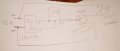
In the drawing is the original idea. Didn't work, so I put a 5v relay module connected to the pnp transistor and the output of the relay connected to the 12v . That didn't work either.
So, I removed the relay. Now I thought I could use a pnp mosfet, but have no idea if it will work.
I thought on the mosfet cause once you turn it on, they stay. I'm thinking once on the next trigger signal will turn it off. But not sure about that.Polish_20230621_220429909.jpg
 

ElectricSpidey

Joined Dec 2, 2017
3,347
Your recreation of my schematic is close but there is a mistake at R3 & R4.

Also, if you replace the MOSFET with a bjt as shown it should be an NPN not a PNP as shown. (but I would stick with a NMOS)

If you are really serious about trying the circuit I can show you how the connections are done to the ICs, but I think if you check the data sheets you could probably figure it out yourself.

JFTR MOSFETS don't stay on by themselves, especially if driven by a high and low signal such as provided by that receiver.
 

Thread Starter

jriofrio

Joined Dec 8, 2014
93
Your recreation of my schematic is close but there is a mistake at R3 & R4.

Also, if you replace the MOSFET with a bjt as shown it should be an NPN not a PNP as shown. (but I would stick with a NMOS)

If you are really serious about trying the circuit I can show you how the connections are done to the ICs, but I think if you check the data sheets you could probably figure it out yourself.

JFTR MOSFETS don't stay on by themselves, especially if driven by a high and low signal such as provided by that receiver.
I appreciate very much your help, I am just really surprised that there's not a simpler solution.
Sometime ago I did something similar, I bought a 5v module with the IR receiver and the relay to switch a 120Vac lamp. The only complication was to put together the IR module with a 5v USB power supply, cause I couldn't make it fit in the lamp, I have to make a box for it (no pretty but it works).
I thought this time around would be simpler cause it is 12vdc lamp, just get a 12 to 5v dc/dc and a transistor with a few resistor will do the job and will make it look pretty this time. Have no idea of these complication will arrive.
Anyway, I am thankful for your willingness to help. Appreciate it very much.
 

ElectricSpidey

Joined Dec 2, 2017
3,347
Last edited:

Thread Starter

jriofrio

Joined Dec 8, 2014
93
Maybe your best bet is to just go with something like this.

If you are careful, you could probably change the location of the photodiode/phototransistor (or whatever the optical component is)

Amazon.com: Remote Control Relay Module, Icstation 12V 1 Channel IR Remote Control Power Switch Self Locking : Electronics
Well, I was trying not to use something like that because of the size with the relay.
I actually used the same exact module in a 120vac lamp sometime ago. This time around I thought using fewer and smaller components because not AC to deal with.
Would you please explain why it is problematic to switc on/off the IR signal using a mosfet or a transistor. If the frequency of the IR signal is the problem, is there a way to control it with RC components?. I would like to understand the reasons.... Good night
 

sghioto

Joined Dec 31, 2017
8,729
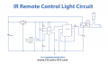
I found that circuit you mentioned using a 555 with the 4017.
Should work. Replace Q1 with a mosfet to drive the LED lamp directly eliminating the relay.
1687408195533.png
 
Last edited:

ElectricSpidey

Joined Dec 2, 2017
3,347
You could place an RC network ahead of a transistor to drive your lamp LED but the only thing that would achieve is to stop the blinking while you have the remote button pressed, the lamp would still turn off when you lift the button.

@sghioto

So, the 555-4017 circuit works as follows?

The sensor provides low pulses that trigger a one-shot. (with a time longer than the pulse sequence)
The one-shot clocks the 4017.
The 4017 has its reset pin connected to output #2.

Is that correct?

Nevermind...I see you posted the circuit.
 
Last edited:

Thread Starter

jriofrio

Joined Dec 8, 2014
93
You could place an RC network ahead of a transistor to drive your lamp LED but the only thing that would achieve is to stop the blinking while you have the remote button pressed, the lamp would still turn off when you lift the button.

@sghioto

So, the 555-4017 circuit works as follows?

The sensor provides low pulses that trigger a one-shot. (with a time longer than the pulse sequence)
The one-shot clocks the 4017.
The 4017 has its reset pin connected to output #2.

Is that correct?
In you referring to pin 15 connected to pin 4 pn the 4017, yeah that's correct. I have not tried that circuit thinking it should be a simpler solution.
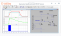
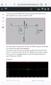
Looking through some designs that I downloaded, I found a couple that I would like you take a look at them, if is ok with you of course. Please let me know if either of both will do the switching.
In the first one, I would need to replace the IR receiver with the 1738. Would it work?
The second one, I am not sure if the input (ON - OFF) it is referring to the output of a IR receiver.
Please take a look and see if either one will accomplish the switching.
Thank you for your time... Screenshot_20230620-213121.pngScreenshot_20230620-205037.png
 
Last edited:

ElectricSpidey

Joined Dec 2, 2017
3,347
Nothing you posted above will do what you want.

At quick glance one looks like an inverted driver and the other looks like non-inverted with some sort of delay.

I'm going to give something I thought of last night a try...will let you know.
 

sghioto

Joined Dec 31, 2017
8,729
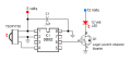
Just for the record here's a circuit showing how simple it can be using a Picaxe 08M2 microchip with code.
1687446007956.png
Code
1) main: if pin3 = 0 and b0 = 0 then high 1
2) pause 1000
3) b0 = 1
4) endif
5) if pin3 = 0 and b0 = 1 then low 1
6) pause 1000
7) b0 = 0
8) endif
9) goto main
 
Last edited:

sghioto

Joined Dec 31, 2017
8,729
Yes it does toggle the LED as required.
Do you understand the Picaxe coding format?
I didn't want to get into a line by line explanation unless the TS ask me to.
 
Last edited:

BobTPH

Joined Jun 5, 2013
11,601
I do not know the language, that is why I asked you you explain it.

Here is what I think the TS is asking for:

One press on remote turns the light on. The next press turns it off.

And the input is from a TSOP receiving a signal from a TV remote, which is a repeating sequence of short and long pulses at 38KHz.
 

sghioto

Joined Dec 31, 2017
8,729
I do not know the language, that is why I asked you you explain it.
OK then for your benefit.
On power up all outputs are Low and all variables are set at 0
The output of the TSOP1738 is normally High when not receiving an IR signal.
The first press on the remote sends a series of pulses. First Low side of a pulse sets output 1 (leg 6) High turning on the mosfet.
Pause 1000 gives a 1 second delay for plenty of time to release the button on the remote before the code proceeds to line 5
B0 = 1 provides the logic needed so the next press sets output 1 Low without any delay.
 

Thread Starter

jriofrio

Joined Dec 8, 2014
93
Just for the record here's a circuit showing how simple it can be using a Picaxe 08M2 microchip with code.
View attachment 296896
Code
1) main: if pin3 = 0 and b0 = 0 then high 1
2) pause 1000
3) b0 = 1
4) endif
5) if pin3 = 0 and b0 = 1 then low 1
6) pause 1000
7) b0 = 0
8) endif
9) goto main
Well, it looks promising. What will be needed in order to program the MCU?
I do have n channel mosfet (irf9z24n) that I can use it here.
The code is short and simple enough.
If I figure in how I can program it, I will definitely will try it.
Thank you for your time and effort.
 
Top