Two LEDs and 2 SPST. Four states?

Thread Starter

gruzlor

Joined Sep 23, 2012
3
Hello,

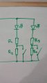
Newbie question I have a device that have two SPST relays that I control. From these relays, I would like to control the ON/OFF states of two LEDs (red and green) and a high/low brightness state. This gives four possibilities:
  • Red High brightness
  • Red Low brightness
  • Green High brightness
  • Green Low brightness

So far, I can imagine using a relay to divide the current and the other relay to turn ON/OFF a single LED. But that's half of the job and using a Arduino for that feature seems overkilled. Any help would be much appreciated.

Thanks in advance!
 

jpanhalt

Joined Jan 18, 2008
11,087
Welcome to AAC.

Sounds like 6 states: you forgot red off and green off. Must you be able to control each state completely independently? That may be tough to do with just 2 SPST switches. Using SPDT may give you a better chance. EDIT: SPDT center off

Can you use other components, like diodes and resistors?
 
Last edited:

AnalogKid

Joined Aug 1, 2013
11,042
EDIT: this (excellent) solution assumes that both relays are SPDT. I misread the original question. The problem can be solved with only SPST relays ***if*** one additional diode is added to the circuit.

The schematic in #3 has both LEDs on all the time, but in different brightnesses. If you want the four states to be mutually exclusive - that is, when the red LED is on at either brightness, the green LED is off - then:

relay 1 pole 1: Vcc (positive supply voltage)
relay 1 throw 1: red LED anode
relay 1 throw 2: green LED anode

Both LED cathodes connected together. This node is connected to two resistors, one for each brightness level. The other ends of these resistors go to relay 2.

relay 2 pole 1: GND
relay 2 throw 1: high brightness current limiting resistor
relay 2 throw 2: low brightness current limiting resistor

Relay 1 selects which LED is on. Relay two controls brightness by selecting one of two the current limiting resistors, which set the brightness of whichever LED is selected by relay 1.

There are at least two other ways to do this by changing how relay 2 is used, but they both have one resistor in the circuit at all times, and the other resistor switched either in series or in parallel. For both methods, selecting the resistors to get the brightnesses you want is a bit more difficult, because one resistor affects both brightness levels.

ak
 
Last edited:

AnalogKid

Joined Aug 1, 2013
11,042
Here is a first-pass at a SPST solution.

The D3 forward voltage drop (Vf) is less than the combined Vf's of D1 plus D2. When K1 is energized, D3 effectively "shorts out" D1, stealing away all of the available current. K2 changes the brightness by shorting out one of the current limiting resistors. R1 alone sets the high brightness. R1+R2 sets the low brightness.

The off-off state (both relays unenergized) is Red LED on low. Swapping the two LEDs changes this condition to green LED on low. If you want the off-off state to be at high brightness, K2 and R2 can be rearranged such that K2 switches R2 in parallel with R1 rather than in series with it. With this change, R1 alone sets the low brightness, and R1 || R2 (R1 in parallel with R2) sets the high brightness.

ak
LED-Relay-Switching-1.gif
 
Last edited:

click_here

Joined Sep 22, 2020
548
If you don't want to program anything it sounds like a decade counter is what you are after - Every time you close the SPST you can move through different states.

The outputs could be used to control the LED part of the circuit.

i.e. High, off, low, off, high, off, ...
 

AnalogKid

Joined Aug 1, 2013
11,042
High, off, low, off, high, off, ...
That is not the requirement in post #1.

A counter, or any other kind of sequential circuit, does not allow for the direct transition from any of the four states to any other one. Worst case with a Johnson counter (CD4017) is three relay closures to get from where you are to where you want to be. Also, the counter clock input would have to be debounced.

Also, how would sequential counter outputs address the brightness requirement?

Per post #1, the TS already has a way to drive two SPST relays, two LEDs, and two current limiting resistors. The task is to get random access to any of the four listed states in a simple and reliable way. IOW, a circuit that is not
overkilled
I think adding one diode is a minimal solution.

ak

ps. There is a counter solution that almost gets there. Actually, a flipflop solution. One relay could clock a toggle flipflop (ex. 1/2 of a CD4013) with the Q and Q- outputs driving the LEDs, while the other relay switches the current limiting as above. Three things about this: 1) again you have to debounce the ff clock input (more parts); 2) depending on the desired LED current, you probably have to add LED driver transistors to the ff outputs; 3) without physically looking at the LEDs, there is no way to know from just the control signals which LED is lit.
 
Last edited:

Thread Starter

gruzlor

Joined Sep 23, 2012
3
Many thank for all your replies. Much appreciated! I couldn't check the thread earlier but my 1st post was obviously misleading. The LEDs are to show occupancy of a room - so one LED should shine at a time - still 4 states though for the system (because of the 2x SPST):
  • Red High brightness - Green off
  • Red Low brightness - Green off
  • Green High brightness - Red off
  • Green Low brightness - Red off

I feel the solution suggested by AnalogKid (thx!) is rather close to this result. I need to scratch my head a bit more on this one. Shouldn't be that hard, right?

Thanks again!
 

jpanhalt

Joined Jan 18, 2008
11,087
Don't understand your purpose, but in my experience brightness is quite subjective. Color is more objective. At one place with which I am familiar, different color flags were used. Each color had a specific meaning.

May I suggest that you consider 4 leds: Red, Green, Yellow, and Blue or White? You still have only one on at a time. Where does the requirement for 2 SPST switches come from? Is this a real problem in design or homework that stipulates SPST instead of DPST, SPDT, or DPDT?
 

click_here

Joined Sep 22, 2020
548
I didn't know that when one LED was on the other was off, so I was just suggesting a way of moving through more states.

Of course it doesn't matter now, but to answer your questions:
The way that the output can change the brightness is by either switching on a MOSFET that shunts a resistor, or by changing the path to ground to flow through an extra resistor.

After that clarification I can see that AnalogKid's solution is what they wanted, but I agree with jpanhalt that brightness is subjective - It might be a good idea to consider a flashing LED instead
 

eetech00

Joined Jun 8, 2013
3,949
I didn't know that when one LED was on the other was off, so I was just suggesting a way of moving through more states.

Of course it doesn't matter now, but to answer your questions:
The way that the output can change the brightness is by either switching on a MOSFET that shunts a resistor, or by changing the path to ground to flow through an extra resistor.

After that clarification I can see that AnalogKid's solution is what they wanted, but I agree with jpanhalt that brightness is subjective - It might be a good idea to consider a flashing LED instead
or....you might consider a bargraph style display with discrete LEDs arranged in a vertical column. Maybe an LM3914 driver..
 

Thread Starter

gruzlor

Joined Sep 23, 2012
3
Thanks again for your replies. Just to give you some insights: I have received an old door controller which has 2x SPST and I would like to use it for a Do Not Disturb LED status - which changes brightness depending on the time of the day. Hence my request above. With your inputs, I am now doubting between a microcontroller and AnalogKid's design. For sure, I have enough info for now. Thanks again for your help!
 

click_here

Joined Sep 22, 2020
548
How are you going to measure the time of the day? If you are going to be using a microcontroller to do that anyway...

However, looking at it another way, wouldn't you be better setting the LED brightness based on the brightness of the room? That way you don't have to worry about the changing sunrise/sunset times over the year. You also could have it automatically adjust for a dark cloudy day (vs a bright sunny day).

You could do this with either a microcontroller or analogue circuitry - Just use an LDR and make sure that your LED doesn't point at it
 
Top