In the circuit shown in post #61, if the "VGND" connection is not extended to the junction of R1 and R2, so that the voltage is about 6 volts above the supply negative, the operation will not be correct. That may explain it not working. I have not examined the data sheet for the NE5532 op-amp and so I do not know if the frequency response is adequate.
In the circuit shown in post #61, if the "VGND" connection is not extended to the junction of R1 and R2, so that the voltage is about 6 volts above the supply negative, the operation will not be correct. That may explain it not working. I have not examined the data sheet for the NE5532 op-amp and so I do not know if the frequency response is adequate.
Hi eric,
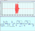
Seems like we have actual huge gain here.
Blue traces are the signal on piezo pin.
I can not understand why is that works on the old circuit and not the newer one.
Do I over gain it ?
Hi dem,
If the lower image, yellow trace, is the amplifier output, it is oscillating.
Show me what changes you have made , post asc circuit.
E BTW: if your circuit wiring is too long and 'messy' then with a high gain amplifier, it will most likely oscillate or be unstable.
Hi eric, outputs are from this circuit. Yellow traces are amplifier output.
Second image is to show gain is always so high and any echo can not be dedected.
Hi eric, outputs are from this circuit. Yellow traces are amplifier output.
Second image is to show gain is always so high and any echo can not be dedected.
Hi dem,
Read my added note:
E BTW: if your circuit wiring is too long and 'messy' then with a high gain amplifier, it will most likely oscillate or be unstable.
Hi dem,
Read my added note:
E BTW: if your circuit wiring is too long and 'messy' then with a high gain amplifier, it will most likely oscillate or be unstable.
Hi dem,
I have seen worse.
An important point is that the circuit should have capacitor decoupling on the bread board.
Add say 100uF and a couple of 100nF capacitors on the 12V to 0V supply lines.
If that bottom left-hand corner is a 12V linear regulator, it should have at least a 100nF on the input and output pins to 0V.
E
Is that bottom right the IRF MOSFET?
Bu görsele daha detaylı bakacağım, bakalım başka sorunlar var mı.
Hi dem,
I have seen worse.
An important point is that the circuit should have capacitor decoupling on the bread board.
Add say 100uF and a couple of 100nF capacitors on the 12V to 0V supply lines.
If that bottom left-hand corner is a 12V linear regulator, it should have at least a 100nF on the input and output pins to 0V.
E
Bu görsele daha detaylı bakacağım, bakalım başka sorunlar var mı.
Hi eric, you are right and I have added it rn but there is no change in the result.
I used same powering and same transmitter built in the circuit where I got the result in this picture:
In this echo is so clearly gained from any other signal.
I also made a new prototype now, but I am not available to try for few hours.
Hi eric, you are right and I have added it rn but there is no change in the result.
I used same powering and same transmitter built in the circuit where I got the result in this picture:
In this echo is so clearly gained from any other signal. View attachment 327394
I also made a new prototype now, but I am not available to try for few hours. View attachment 327400
Hi Eric and all , I've been doing experiments over my circuit designs and found out some effective phenomenas.
Before sharing the information I obtained from experiments with you, I would like to share the circuit and ossciloscope output.
The circuit in which the experimental results were obtained is shown in Figure 1. In result ,it is still hard to measure any range lower than 60cms , but at the point we have very large echo signal.
While conducting the experiments, I found that using separate op-amps instead of dual packages eliminated a major issue. Our echo signal is no more getting missed.
I've tried using opamps on dual packages of each NE5532 and LF353 and have got no result. But when I connect separately - one opamp from each packages - I get the result I want. At this point I do not know why is this happenning. Datasheets say that the predicted supply current in the Ltspice is low enough to be supplied.
To measure any distance lower than 60cms , I consider that time dependent gain might be usefull.
Hi demir,
Pleased to hear you are making progress with the project.
You should now consider using a Comparator IC that will turn the low level output Echo signal into an MCU logic level.
Using that logic level, you can then measure the TOF from TX to RX time by using the MCU and program.
How do you plan to display that TOF and Distance?
E
Hi demir,
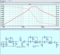
As a reference example for study, this is a simple Band Pass filter for 40kHz.
It uses standard resistor and capacitor values and an AD822 OPA, which is in the LTSpice OPA's folder.
E
Hi demir,
As a reference example for study, this is a simple Band Pass filter for 40kHz.
It uses standard resistor and capacitor values and an AD822 OPA, which is in the LTSpice OPA's folder.
E
Hi Eric, for now just calculating the distance is enough. I do not have an plan to display yet.
Why do you think that circuit does not work when I use single Ic ?
I also will check the filter you publish thank you.
Also ,I stil can not measure distances under 60cms, this time mostly due to overgaining.
 Facebook
 Google
 GitHub
 Linkedin


")