IRLZ44N and IR2110 not switching properly for generating magnetic field

Thread Starter

cisco100200

Joined Jul 10, 2026
17
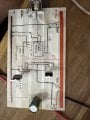
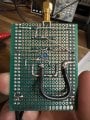
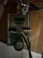
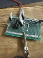
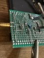
Hi, I'm having issues with a IR2110 based MOSFET driver circuit, specifically IRLZ44N, the signal comes in from my signal generator at 5vpp, then goes into pin 12 on the IR2110 and reaches it correctly, pin 11 and 10 to GND, pin 9 to pin 3 on the 7805 5v regulator, pin 3 is vcc so it goes to the 15v rail, pin 2 to gnd, and pin 1 to the gates of both MOSFETS, connected via a 10ohm Resistor, and both mosfets are in parallel so G to G , D to D, S to S, and the Sources are tied to ground, and I've placed a shottky diode on the load output, the load is a resonant coil 0.47mH and 0.5Ohm resistant large loop but when the 5Vpp square wave signal is inputted the mosfets are not switching correctly one side of the load is connected to the drains and the other side o the load is on the 15v rail with the diode across it , any ideas or help would be appreciated, thanks guys this is my first perfboard
 

Thread Starter

cisco100200

Joined Jul 10, 2026
17
I disconnected the wires from the chip and cleaned it up and it’s saying there is a short when even have no chip in and no wires connected to the chip it’s weird I think the mosfets are toast they showing continuity on all pins
 

Thread Starter

cisco100200

Joined Jul 10, 2026
17
Powered on fine with no IC in then I powered off and Inserted IC and the magic smoke came out and the IR2110 let out some magic smoke, that’s the 7th IR2110 I’ve been through now over the past two days something is wrong
 

Attachments

Thread Starter

cisco100200

Joined Jul 10, 2026
17
Okay new IC and new mosfets installed and board powers on with 15v fine now but when I send a signal from signal generator it blows the IR2110 up and I have to replace it
 

Thread Starter

cisco100200

Joined Jul 10, 2026
17
Two things stand out to me. First, you don't need the 7805, pin 9 is perfectly happy being connected to +15V. Secondly, and probably why you keep blowing driver chips, is because your coil protection diode is wired the wrong way round on the board, and shorts the MOSFETS to Gnd as soon as they turn on.
Thank you very much for you reply and help, yes swapping the diode around has now made the IR2110s not blow up and with signal generator off im measuring 13.6v on the common drains, when being powered with my 15v bench supply, and when i input the signal from signal generator, its at 6Vpp square wave into the circuit when it should be 5Vpp or below really to trigger it, and the 13.6v that was on the drains switches over to the gates and is showing 7.3 volts on each of the gates and im doing all of this with no load connected, i presume once i connect the load it will be much more current being drawn from my power supply because now with the board powered on and no signal running from sig gen its showing 0.000A but when i put turn the signal on current goes up to 0.018 so i believe its working, and also is a 220uF LOW-ESR 100V electrolytic capacitor recommended from 15v to ground rail

PS, im too scared to connect my load at the moment to will wait until i hear back from you thank you very much
 

Attachments

Thread Starter

cisco100200

Joined Jul 10, 2026
17
okay what decoupling capacitors from the main power rail, which ones would be recommended values and types please i want thinking 220uF electrolytic 100v and 100nF close to the mosfet bridge?
 

Thread Starter

cisco100200

Joined Jul 10, 2026
17
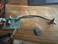
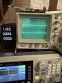
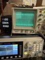
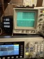
Photo 1 is pin 12 INPUT LIN, photo 2 is pin 1 the LO from the IR2110, and then 3rd photo is the scope probe on the common drains point of the MOSFETS, and this is with no load connected yet just the BNC connector, and no decoupling capacitors and with the 7805 still being used, maybe its causing some ringing or something i dont know
 

Attachments

Last edited:
Top