Facebook
 Google
 GitHub
 Linkedin
Hi,
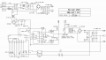
I have built an smps, Half Bridge using SG3525 + IR2110.
It works fine - Except for changing(control) the output voltage by changing the duty cycle.
The nominal dc voltage is 270. Half is 135v
The transformer core is E42/21/15
Primary windings : 20
Secondary 4+4 : gets 32v - needed only 22v
Mosfets : IRF840
I can change the output if a low value res is fixed in parallel to the output filter caps. But this wastes power too much.
I have tried practically everything , changing the frequency, snubbers......, inductor on the output after the bridge diode (dual rail output). etc etc. Nothing helps to control the output.
It seems the power is simply dumped into the caps and it stays there. The change is too slow for the dutycycle to adjust it.
Is there any recipe to control the output in a better way than load resistors ?
The only two things I haven't tried is changing dead time and changing the primary turns. But can any of that truly help eliminate load resistors ?