TR switching and receiving echo signals

Thread Starter

demir-ali

Joined Jul 13, 2024
321
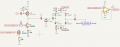
I set this circuit to use piezo as transceiver. I can perfectly transfer the transmitter signal (10 burst pulse) but as transmitter still connected onto piezo , any reveived signal is disappears. When I disconnect the transmitter output and test it by transmitting from another piezo there is no problem with receiving. How can I modify my circuit to receive echo signals ?
Test were made when the switch was disconnected.

THE Y1-CRYSTAL is the piezo in circuit. I do not add any links because it is my design.
as.png
 

sghioto

Joined Dec 31, 2017
8,633
Can you elaborate more on the circuit?
What are D1-D6 for?
Is the TX input where the 10 burst pulses connect?
What switch was disconnected?
Is the piezo a delay component?
 

michael8

Joined Jan 11, 2015
472
I'd think you would need a switch between the transmitter and piezo transceiver in addtion to one in front of
the amplifier. The first is to keep noise/signal from the transmitter out of the receive signal and the 2nd (existing)
to keep the large transmit signal from the receiver input.

I've seen slightly similar to D1-D6 before but they were driven by a current source and D6 is backwards compared to them.
(or D5 and D6 were resistors not diodes). With the current D6 there isn't a current path out of the D's...
 

ericgibbs

Joined Jan 29, 2010
21,390
Hi demir,
What is the resonant frequency of the crystal transducer.?
The diode clamp network is much too complex, it can be simplified.
The series R1, C1 circuit will sink any echo signals, it is effectively in parallel with the crystal.

E
 

Thread Starter

demir-ali

Joined Jul 13, 2024
321
I changed transmitter part to this circuit. 2n2222A is there for to act as current controlled resistance and now I can see waves oncoming from another transmitter with small loss but due to piezos natural response (i guess) i cant see the echo waves.
Echo waves are way more small and piezos self osscilate behaviour blocks the echo I guess.
1720951381942.png
Below , the signal at piezos gate is shown , TR switch is disconnected.
bjt.png
 

Attachments

Thread Starter

demir-ali

Joined Jul 13, 2024
321
Hi demir,
What is the resonant frequency of the crystal transducer.?
The diode clamp network is much too complex, it can be simplified.
The series R1, C1 circuit will sink any echo signals, it is effectively in parallel with the crystal.

E
piezo is a 40khz ultrasonic piezo
 

Thread Starter

demir-ali

Joined Jul 13, 2024
321
I'd think you would need a switch between the transmitter and piezo transceiver in addtion to one in front of
the amplifier. The first is to keep noise/signal from the transmitter out of the receive signal and the 2nd (existing)
to keep the large transmit signal from the receiver input.

I've seen slightly similar to D1-D6 before but they were driven by a current source and D6 is backwards compared to them.
(or D5 and D6 were resistors not diodes). With the current D6 there isn't a current path out of the D's...
i guess i made it in my last update but i did not connect the tr switch yet
 

ericgibbs

Joined Jan 29, 2010
21,390
Hi demir,
What is the Vdd voltage?
Look at this option for the Echo receiver.
BTW: Don't forget the internal diode of your IRF MOSFET.
E
EG57_ 1935.png
 

Thread Starter

demir-ali

Joined Jul 13, 2024
321
Vdd can be set around 9-16 but 9 is prefered. I can try your design but the problem at the moment is seems different I guess. After transmitting , piezo keeps osscilating for a while and any waves incoming in this piece of time is disappears. For next step , before the mcu i do plan to amplify the signal already.
 

ericgibbs

Joined Jan 29, 2010
21,390
Hi dem,
The ringing of the transducer always occurs after the square wave drive stops, that is normal.
As you may know, the signal strength of the echo falls off rapidly with distance.
To correct for this the amplifier has to have sweep gain, the amplifier gain increases with time after the transmit pulses stop.
Also it is common to have an echo suppression period after the transmit pulses stop.
E
 

Thread Starter

demir-ali

Joined Jul 13, 2024
321
Hi dem,
The ringing of the transducer always occurs after the square wave drive stops, that is normal.
As you may know, the signal strength of the echo falls off rapidly with distance.
To correct for this the amplifier has to have sweep gain, the amplifier gain increases with time after the transmit pulses stop.
Also it is common to have an echo suppression period after the transmit pulses stop.
E
Hi Eric , as I understand your suggestion is to set and amplifier at the output at piezo with a sweep gain. I guess the opamp circuit in your previous reply takes the signal , magnitude is limited with Vd-on and sets gain 100. I wonder if this is what you mentioned as sweep gain or may I use and bjt or fet as current-volt controlled resistance in opamp circuit for variable gain. As I am not well experienced and currently trying to learn I wonder many things so please tolerate my questions.
 

ericgibbs

Joined Jan 29, 2010
21,390
Hi dem.
The 100 gain is the first stage.
Assume an echo of 1mV, times 100 is only 100mV.

What is the final amplified signal driving into??
E
 

Thread Starter

demir-ali

Joined Jul 13, 2024
321
The final signal is probably will be driven into a adc and further mcu. I do plan to calculate TOF , time of flight, and measure distance using the TOF. I understood the gain is 100 but have no idea how to set sweep gain. Or may I got you wrong ?
 

ericgibbs

Joined Jan 29, 2010
21,390
Hi dem,
I would suggest, for initial testing, use just the 100 gain OPA.
Measure what the amplified echo signal measures [an oscilloscope is the best measuring method] over a range of different distances and reflecting surfaces, post what you measure.

If you use an MCU you could use an analogue input on interrupt, and measure the time of flight from TX to RX.

E
 

Thread Starter

demir-ali

Joined Jul 13, 2024
321
Hi Eric , I currently have only LM741 as opamp IC. This evening I probably set the circuit and publish outputs again. I have ordered few better opamp ICs , they probabaly arrive tomorrow. I will let you know the updates.
 

michael8

Joined Jan 11, 2015
472
The LM741 doesn't have enough gain at 40KHz for a gain of 100X. It's bandwidth is too low. Also if you
want square 40KHz waves to make it through you need at least the 3rd harmonic too so 120KHz+ bandwidth.
 

Thread Starter

demir-ali

Joined Jul 13, 2024
321
The LM741 doesn't have enough gain at 40KHz for a gain of 100X. It's bandwidth is too low. Also if you
want square 40KHz waves to make it through you need at least the 3rd harmonic too so 120KHz+ bandwidth.
I ordered LF353N which has bandwith of 4mhz and High Slew Rate: 13 V/μs
They probably arrive tomorrow so I share the results with you
 

Thread Starter

demir-ali

Joined Jul 13, 2024
321
I made experiments using LM741. I pictured the output graphs in the circuit built that I got best outputs. Anyways I am still not be able to read the echo wave.
There is the updated circuit below. I named nodes shown in graphics.
receiverdenemesi.png
In the figure below , the signal captured on piezo - NODE A - by blue traces and the signal incoming to LM741 - NODE B - is shown.
NODEAB.png
In the picture below , signal incoming and outcoming from LM741 is shown.
NODE B vs NODE C
NODEBC.png
 
Top