hi dem,
This image copy of yours is looking better, it is typical, but it is clear that the Piezo is not in resonance, at 35kHz
How are you connecting your components to the HC SR04.
Can you post a photo of the project so that I can the connections
E View attachment 327176
Hi , here is the test you mentioned.
I guess I need to note that , the transducer is the receiver part upon the HC-SR04 so I can not tap straight onto the piezo.
I could not decide if the frequency is 40Khz or 4Khz. What I use is something like this. View attachment 326982
Hi Eric , this is the circuit schematics that I used when having this outputs.
But some due to some issue i could not decide what it is at all , output graph frequently breaks towards this and fixes itself then.
Issue is relatively with the impedance at the piezos output node. The frequency it repeats and the time it takes for getting into readable values is depending on the resistor value of R1 . Graph with the issue is below.
Hi demir,
The 741 OPA is not designed to work with a single supply, especially not with a Vdd=2.5V
If you are using the HC-SR04 module, how are you connecting your components to the HC SR04 ?
The SR04 has two piezo's and some electronic components
Post a photo of the project so that I can see how the SR04 is being used.
E
Hi Eric , as I told you before I do not use hc-sr04. I have seperated transducer and all the commections is as same as schematics. There is no more connection. I understand you but I kept following the voltages and some times piezo peaks at the time domain , dampening time gets longer i think and this issue comes up before lm741. My idea to solve this is to recheck circuit to center the waves.
Hi demir,
The 741 OPA is not designed to work with a single supply, especially not with a Vdd=2.5V
If you are using the HC-SR04 module, how are you connecting your components to the HC SR04 ?
The SR04 has two piezo's and some electronic components
Post a photo of the project so that I can see how the SR04 is being used.
E
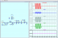
Hi Eric ,
Since I have dual supply opamps , I made a new receiver stage design which opamps are driven using virtual ground method.
Here Is the circuit and the AC analysis.
The issue is , eventhough I set gain lower to be sure all I see on the ossiloscope is a high gained noise but not the echo.
Could you review pls ?
Or may should I try this one ?
Hi demir,
This is your circuit, added some Node names to make it easier to see which plot is which.
As a quick test, plot the VGND node, it is not really a virtual ground.
Use AC=1 for dB plot values.
E
BTW: Consider a Band Pass filter, say 30kHz through 50kHz
It is not a college assignment at all. I'm not being scored on this. Anyways, I still prefer you giving me hints because my purpose is to learn before accomplishing the project. The way we got here, I learned a lot and this is what I want. I will try some changes on my circuit and let you know. Thanks for keeping following.
Many years ago I built a sonar system for use in air, not water.
For the T/R arrangement I used a bridge circuit to cancel the transmitted signal entering the receive amplifier. That worked but it was quite inefficient.
In your arrangement, instead of the diodes serving to clamp the Tx pulse, you could forward bias a diode quite heavily and by pass the pulse more completely.
Hi sir , I have tried both single diode biasing and bridge method but the issue I have is any echo wave outcoming has very low amplitude and I need to amplify it. But I dont want to any noise to be amplified. In previous circuit , I could read echo at the out of amplifying stage clearly but , opamps in the circuit was not driven correct and the minimum distance I could measure was 60cm.
 Facebook
 Google
 GitHub
 Linkedin