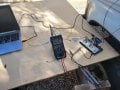
Tachometer suddenly died, wondering if the chip is likely still operational.

Nice. Is that your test meter or the actual vehicle meter? Sounds like it’s your actual vehicle meter. Maybe it’s more linear than originally thought. And are you driving it with code that generates PWM according to the position of a potentiometer, or an actual short pulse from another UNO, or even a real distributor pulse?

All those steps would be worth trying with the UNO as a step by step approach to the end game.
 

Thread Starter

Stuntman225

Joined Apr 28, 2026
76
Nice. Is that your test meter or the actual vehicle meter? Sounds like it’s your actual vehicle meter. Maybe it’s more linear than originally thought. And are you driving it with code that generates PWM according to the position of a potentiometer, or an actual short pulse from another UNO, or even a real distributor pulse?

All those steps would be worth trying with the UNO as a step by step approach to the end game.
The test setup has a signal generator, and I just got code working that reads the input signal, generates an rpm value, and interpolates that to a 0 - 255 pwm signal. And yes, I am testing my gauge now.
I did try for a little bit with linear math, but it was going to be off by about 300 rpm in the middle of it's range.20260515_164913.jpg
 

Thread Starter

Stuntman225

Joined Apr 28, 2026
76
I got a chance to test everything on my truck, and there are a few problems. One, the input signal is quite uneven, with the Arduino hovering the rpm value in the right spot but not able to hit it. I think it is likely due to the input signal not quite being 5v when the coil is resting. I think i can mostly fix it in code, but i would like to know if you have any ideas on how to filter it with hardware. The other problem is the coil ground isn't isolated enough from the Attiny85's but i think rewiring the grounds can fix that.

img_06.jpg
20260518_085523.jpg
 

Thread Starter

Stuntman225

Joined Apr 28, 2026
76
I played around with the grounding positions, and the attiny85 no longer gets any outside interference causing the needle to move when the signal wire is unplugged from the attiny85.
I got some better pictures of the input signal to the attiny85. The picture are the signal at the attiny's input pin.
img_01.jpgimg_02.jpg

Edit: From coil
img_04.jpg

Edit 2: current schematic. (without clock)
V1.1 board.png
 
Last edited:
I still wonder if a different supply for the meter would make sense, ideally around 9V but just using another 7805 with 5V if you have one might make a difference. I like the idea of a resistor change to modify for different number of cylinders if you are thinking of a more universal solution

if the input is being triggered by the ringing of the distributor signal maybe a zener diode in series with the opto diode would help stop the opto being triggered by the lower voltage peaks. Also increasing the value of the input resistors? Overall, great to see you’ve got it working!
 
Last edited:

Thread Starter

Stuntman225

Joined Apr 28, 2026
76
I still wonder if a different supply for the meter would make sense, ideally around 9V but just using another 7805 with 5V if you have one might make a difference. I like the idea of a resistor change to modify for different number of cylinders if you are thinking of a more universal solution

if the input is being triggered by the ringing of the distributor signal maybe a zener diode in series with the opto diode would help stop the opto being triggered by the lower voltage peaks. Also increasing the value of the input resistors? Overall, great to see you’ve got it working!
I've been playing around with a circuit board with the same dimensions as the previous board hooked to the tach. It's likely that i could make it bigger, but at it's current size it would be difficult to add another voltage regulator to it. Also, I don't think the 5v is causing the meter bounce. I'll keep a zener in mind. I don't currently have any, but i'll likely have to make a new order off Mouser soon.
I'm playing around with using a different input detection method for the code, but reading and learning takes time.
Maybe just try a bigger value of input resistance? And/or use the battery voltage instead of 5V for the meter with a bigger series resistor. With the engine running the voltage should be stable - just to check if the meter still jumps about. And I can’t recall if we discussed, do you have a 2mS time after a spark is acknowledged to avoid multiple reads from one spark? In my code the main loop which runs fast ignores a spark unless it sees three consecutive reads to avoid spurious noise. But I’ve only checked it on the bench. Just noticed, the diode is across the meter in series with the 100R resistor and 50R trimpot - better I think if it's just across the meter. And a 100nF capacitor across the meter too?

Here is my code written in Arduino IDE. I recall you said you are using python but it may still be useful for you to see this - it's easy to follow. Basically, it needs to see 3 consecutive low inputs to register a spark and it ignores subsequent readings for 2ms which could probably be increased to 3 or even 3.5ms where 8000 RPM has an interval of 3.75ms.
 

Attachments

Last edited:

Thread Starter

Stuntman225

Joined Apr 28, 2026
76
Maybe just try a bigger value of input resistance? And/or use the battery voltage instead of 5V for the meter with a bigger series resistor. With the engine running the voltage should be stable - just to check if the meter still jumps about. And I can’t recall if we discussed, do you have a 2mS time after a spark is acknowledged to avoid multiple reads from one spark? In my code the main loop which runs fast ignores a spark unless it sees three consecutive reads to avoid spurious noise. But I’ve only checked it on the bench. Just noticed, the diode is across the meter in series with the 100R resistor and 50R trimpot - better I think if it's just across the meter. And a 100nF capacitor across the meter too?

Here is my code written in Arduino IDE. I recall you said you are using python but it may still be useful for you to see this - it's easy to follow. Basically, it needs to see 3 consecutive low inputs to register a spark and it ignores subsequent readings for 2ms which could probably be increased to 3 or even 3.5ms where 8000 RPM has an interval of 3.75ms.
The first Uno that i planned on using used python, I switched to a regular uno which uses C++. (I'm coding in C++).
I'm currently still running the meter off of 5v from an Uno that's plugged into my laptop. I think the main problem is that the Arduino side of the optocoupler is not a clean square wave. I'll experiment with your code.
 
I think the main problem is that the Arduino side of the optocoupler is not a clean square wave. I'll experiment with your code.
It certainly isn't a clean square wave from the distributor. The idea of looking for three consecutive low readings on the input pin is to ignore noise. I'd also try changing the 5nF capacitor to 20nF. If you try driving the meter with a constant value of 128 or thereabouts (just going around the code which looks at the input pin and changes the pwm value) does the meter still jump about near 4000 RPM? My generator is just a UNO driving a 1ms pulse and waiting for the interval before the next pulse, determined by a potentiometer.
 

Thread Starter

Stuntman225

Joined Apr 28, 2026
76
It certainly isn't a clean square wave from the distributor. The idea of looking for three consecutive low readings on the input pin is to ignore noise. I'd also try changing the 5nF capacitor to 20nF. If you try driving the meter with a constant value of 128 or thereabouts (just going around the code which looks at the input pin and changes the pwm value) does the meter still jump about near 4000 RPM? My generator is just a UNO driving a 1ms pulse and waiting for the interval before the next pulse, determined by a potentiometer.
The setup works properly on the bench, just the Arduino can't get a good read on the input coming from the coil. It works perfect with any square wave signal.
 

Thread Starter

Stuntman225

Joined Apr 28, 2026
76
I did some testing with some parts that i have, and the solution erratic reading is either an extra circuit, or coding proper interrupts.
I did attach the 5v regulator for this test, and if i run the tach signal wire from the optocoupler to Attiny far away from the power lines on the bread board, (Unplugged because the code right now doesn't work properly) there is no interference causing the needle to hover or do behave erratically. That's at least good news for the final circuit design.
 
Are you still testing with the UNO? My code won’t work with the UNO without changing pin assignments. And watch out for where my text file does carriage returns where I’ve inserted comments. The compiler will alert you to those if you don’t spot them.

What does the signal from the coil look like on an oscilloscope on the processor side of the opto with a time base which shows amplitude and width of the pulse?
 

Thread Starter

Stuntman225

Joined Apr 28, 2026
76
Are you still testing with the UNO? My code won’t work with the UNO without changing pin assignments. And watch out for where my text file does carriage returns where I’ve inserted comments. The compiler will alert you to those if you don’t spot them.
I've tested with both the Attiny85 and the Uno, all of the code that I've tested works fine on the bench, but poorly on the truck.
What does the signal from the coil look like on an oscilloscope on the processor side of the opto with a time base which shows amplitude and width of the pulse?
I'll get better pictures of that today.
 

Thread Starter

Stuntman225

Joined Apr 28, 2026
76
I found a circuit design for turning coil neg into square wave.
https://github.com/autosportlabs/CoilX
I did some reading on Schmitt triggers and they seem like the solution to my problem. I'm going to get the parts and really hope that it will give a square wave output.
I will keep working on code solutions until parts get here
 
Last edited:
I really think it’s worth trying to understand why the coil pulse is not getting through. Knowing the shape and duration of the pulse before and after the opto is crucial. It may be clamped to 80 volts at the coil, which I doubt for an older vehicle, but if it is then the input resistance needs to be reduced to make sure the opto gets enough current. Generally you are very close - understanding why what you have isn’t working would be my preferred route before looking at alternative hardware.
 

Thread Starter

Stuntman225

Joined Apr 28, 2026
76
I really think it’s worth trying to understand why the coil pulse is not getting through. Knowing the shape and duration of the pulse before and after the opto is crucial. It may be clamped to 80 volts at the coil, which I doubt for an older vehicle, but if it is then the input resistance needs to be reduced to make sure the opto gets enough current. Generally you are very close - understanding why what you have isn’t working would be my preferred route before looking at alternative hardware.
This is the signal getting to the Arduino though the optocoupler. I believe that it's just to inconsistent to properly read. If you look closely, it's possible to see lots of signal oscillations when the coil is drawn down to fire.
1779296956211.png
 
I need to think about this some more, but it looks like the opto is not pulling the input pin low enough. Maybe try changing the 4K7 pullup resistor to 22K or leave it out and keep the internal pull up. How are you grounding?
 

Thread Starter

Stuntman225

Joined Apr 28, 2026
76
I need to think about this some more, but it looks like the opto is not pulling the input pin low enough. Maybe try changing the 4K7 pullup resistor to 22K or leave it out and keep the internal pull up. How are you grounding?
The coil side of the optocoupler is where all the grounds meet up, so the 2 voltages can be as separated as possible. (The green lead is ground)
I tried the building the part of the CoilX circuit that goes into the optocoupler, and the signal that went to the Arduino only went high when the coil actually triggered. The 'high' portion of the signal still had lots of oscillations, but the 'low' portion of the signal didn't drop when the coil charged.
20260521_081749.jpg
 
Mmm, I thought you were building it on a PCB. I’m not keen on using that type of prototype system at the best of times, but especially when there are high frequency spikes flying around. I urge you to do a careful compact layout on strip board with the processor in a turned pin socket so you can take it out for uploading code.

Then start soldering the components for the 5V supply, the input resistors, diode and small capacitor and the opto and the pull up resistor just to check the shape of the voltage at the collector of the opto when running the engine. From what you’ve said and shown, this is the part of the circuit which isn’t working. The collector should drop from 5V to around 0.3V for around 1ms when viewed on the oscilloscope. Try without the 5nF capacitor first. Your call, but that’s what I would do - step by step.
 
Top