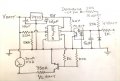
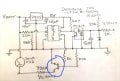
Tachometer suddenly died, wondering if the chip is likely still operational.

Thread Starter

Stuntman225

Joined Apr 28, 2026
76
This may be of use to you .

Thanks, his first tach is acting kind of like mine, so it definitely seems that i need a new board. I would actually be quite tempted to scavenge tachometers at the junk yards, but none of my local yards carry more than 1 80s Toyota at a time.
 

Thread Starter

Stuntman225

Joined Apr 28, 2026
76
Just took some needle measurements.
2v, 1.5k ohms = 250 rpm
3v, 1.5k ohms = 500 rpm
3v, 1k ohms= 750 rpm
3v, 870 ohms= 980 rpm
3v, 666 ohms= 1200 rpm
3v, 430 ohms= 1500 rpm
3v, 366 ohms = 1750 rpm
3v, 330 ohms= 1950 rpm
I would try some lower value resistors, but i don't have any. The gauge maxes out at 8000 rpm, with the needle seeming to max out at 8500 rpm when i manually move it to the end of it's travel.
 

Jerry-Hat-Trick

Joined Aug 31, 2022
840
Just took some needle measurements.
2v, 1.5k ohms = 250 rpm
3v, 1.5k ohms = 500 rpm
3v, 1k ohms= 750 rpm
3v, 870 ohms= 980 rpm
3v, 666 ohms= 1200 rpm
3v, 430 ohms= 1500 rpm
3v, 366 ohms = 1750 rpm
3v, 330 ohms= 1950 rpm
I would try some lower value resistors, but i don't have any. The gauge maxes out at 8000 rpm, with the needle seeming to max out at 8500 rpm when i manually move it to the end of it's travel.
Not as linear as I’d hoped, but older tachometers are typically not very accurate. It could be a 25mA or 30mA full scale meter. Maybe you have a 5V phone charger available to try with your 330R resistor in parallel with 366 or another 330? It’d be nice to find a way to gently increase the current to approach full scale.

Using a processor like an ATtiny85 to count the pulses and drive a PWM output based on a lookup table would be a nice solution which could be calibrated
 

Thread Starter

Stuntman225

Joined Apr 28, 2026
76
Not as linear as I’d hoped, but older tachometers are typically not very accurate. It could be a 25mA or 30mA full scale meter. Maybe you have a 5V phone charger available to try with your 330R resistor in parallel with 366 or another 330? It’d be nice to find a way to gently increase the current to approach full scale.

Using a processor like an ATtiny85 to count the pulses and drive a PWM output based on a lookup table would be a nice solution which could be calibrated
I found another power supply which i could use. Here's a lot more numbers
5v, 1870 ohm = 625 rpm
5v, 1500 ohm = 975 rpm
5v, 1000 ohm = 1600 rpm
5v, 630 ohm = 2200 rpm
5v, 390 ohm = 3575 rpm
5v, 330 ohm = 4175 rpm

7.5v, 1500 ohm = 1725 rpm
7.5v, 1000 ohm = 2250 rpm
7.5v, 667 ohm = 3600 rpm
7.5v, 390 ohm = 5600 rpm
7.5v, 330 ohm = 6200 rpm

9v, 1500 ohm = 2000 rpm
9v, 1000 ohm = 3100 rpm
9v, 667 ohm = 4225 rpm
9v, 390 ohm = 6650 rpm
9v, 330 ohm = 7600 rpm
 

Jerry-Hat-Trick

Joined Aug 31, 2022
840
Still surprisingly non linear, but 9V through 330 ohm is 27.27mA which really suggests the meter is around 30mA FSD. Is the signal for the Tacho coming from the minus terminal of the coil and how many cylinders? Sorry if I missed this somewhere in the thread. To deal with the non-linearity I hugely favour a processor based solution.
 

Thread Starter

Stuntman225

Joined Apr 28, 2026
76
Still surprisingly non linear, but 9V through 330 ohm is 27.27mA which really suggests the meter is around 30mA FSD. Is the signal for the Tacho coming from the minus terminal of the coil and how many cylinders? Sorry if I missed this somewhere in the thread. To deal with the non-linearity I hugely favour a processor based solution.
It's a coil negative tachometer, on a 4 cylinder (22re).
 

Jerry-Hat-Trick

Joined Aug 31, 2022
840
Thanks, I could sketch a schematic using a ATtiny85 processor but it would need to be programmed. Don’t know if you have the wherewithal to do that? There is a Digispark version on a PCB which can be programmed with the Arduino IDE by plugging directly into a USB port on a PC
 

Thread Starter

Stuntman225

Joined Apr 28, 2026
76
I have the ability to program one right now, my brother is currently messing with a few Arduinos right now. I haven't done coding before, so i am little hesitant to try and make it work.
 

Jerry-Hat-Trick

Joined Aug 31, 2022
840
Wow, I’m just on my cell so can’t sketch right now, will have a go tomorrow. Ideally use a bare ATtiny85 in a socket and program with an Arduino UNO based programmer. If you or your brother can do that, you’ll have a solution.

Essentially the negative pin of the coil flies up to around 400V positive when the point open so feeding this via a 47K 1W resistor to an opto coupler which causes an interrupt on the processor will allow the frequency to be calculated and a PWM output into the base of an NPN transistor with the meter connected to the battery +ve via a resistor to the collector will show the RPM. Since the battery voltage will vary, measuring this will allow adjustment of the PWM mark/space to compensate.
 

Jerry-Hat-Trick

Joined Aug 31, 2022
840
Here's my schematic. I've never made a tachometer like this so I'd welcome improvements and/or questions

1777915695651.jpeg
The ATtiny85 is powered by a 7805 linear regulator. The potential divider into pin2 allows the processor to measure the actual battery voltage to adjust the PWM mark/space so the reading doesn't change with battery voltage. The two 33K resistors in series need to be 1/2 Watt metal oxide to withstand the high voltage at the distributor. They won't get hot as the average power is quite low. The 1K resistor on the right is just for testing and calibration. When driven by short pulses from another Arduino with a varying frequency you should have enough information from reading the meter position at various frequencies to work out a lookup table which can then be programmed into the ATtiny85.

Hope this makes sense. Ask me if not clear, or please point out my errors!
 

Thread Starter

Stuntman225

Joined Apr 28, 2026
76
Here's my schematic. I've never made a tachometer like this so I'd welcome improvements and/or questions

View attachment 366686
The ATtiny85 is powered by a 7805 linear regulator. The potential divider into pin2 allows the processor to measure the actual battery voltage to adjust the PWM mark/space so the reading doesn't change with battery voltage. The two 33K resistors in series need to be 1/2 Watt metal oxide to withstand the high voltage at the distributor. They won't get hot as the average power is quite low. The 1K resistor on the right is just for testing and calibration. When driven by short pulses from another Arduino with a varying frequency you should have enough information from reading the meter position at various frequencies to work out a lookup table which can then be programmed into the ATtiny85.

Hope this makes sense. Ask me if not clear, or please point out my errors!
I'm no electrical engineer, but I feel that the 12v feeding the gauge should also have a voltage regulator on it, as a car's voltage can vary quite a bit, so that the ATtiny85 can better calculations. My car's voltage can vary from 11.9v to 14.8v.
Also, I believe that there should be a potentiometer somewhere in the circuit to be able to fine tune the meter,
 

Thread Starter

Stuntman225

Joined Apr 28, 2026
76
1777915695651.jpegWhen I was testing the gauge for its range of motion, I found that when I lightly tapped the leads with power that the needle could bounce quite aggressively. I don't know how well a (what I think is a transitor) would work here. I am of the understanding that they work like a mechanical relay, but in a smaller package.
 

Jerry-Hat-Trick

Joined Aug 31, 2022
840
I'm no electrical engineer, but I feel that the 12v feeding the gauge should also have a voltage regulator on it, as a car's voltage can vary quite a bit, so that the ATtiny85 can better calculations. My car's voltage can vary from 11.9v to 14.8v.
Also, I believe that there should be a potentiometer somewhere in the circuit to be able to fine tune the meter,
It would certainly work with a voltage regulator but I don't see the need to add the extra components and it'd need to be something like 10V rather than using the 5V from the 7805. I don't think it's necessary, the code can compensate for the voltage change. A 100R trimpot in series with a 330R resistor replacing the 390R resistor would give some adjustment. I've just noticed, the meter should have a catch diode in parallel with it - my bad - the transistor switches on an off really fast so the meter effectively sees an average voltage between zero and 5V - a standard way of doing a quasi analog output.
 

Thread Starter

Stuntman225

Joined Apr 28, 2026
76
It would certainly work with a voltage regulator but I don't see the need to add the extra components and it'd need to be something like 10V rather than using the 5V from the 7805. I don't think it's necessary, the code can compensate for the voltage change. A 100R trimpot in series with a 330R resistor replacing the 390R resistor would give some adjustment. I've just noticed, the meter should have a catch diode in parallel with it - my bad - the transistor switches on an off really fast so the meter effectively sees an average voltage between zero and 5V - a standard way of doing a quasi analog output.
What would the catch diode be? I've been trying to figure out how they work this evening, and they kind of seem like black magic. Also, is the diode in the schematic a regular diode or a zener diode? Most of the tach schematics that I've seen use zeners, so i just want to double check.
 

Thread Starter

Stuntman225

Joined Apr 28, 2026
76
I figured I should make an update for everyone, as this thread has been all over the place.
Though testing and investigation, I have come to the conclusion that the IC in the tach has died, based on how changing the electrolytic capacitor didn't make it work, the crusties on the board not corroding everything and being non conductive. My first plan to replace the original board with one designed around the LM2917. After doing some testing and finding out that the travel of the gauge was fairly unilinear I shelved that idea and am currently trying do build a board based off of the ATtiny85, as it can be programed to compensate for the gauge's unliterary. I am keeping an eye out at local junk yards for 80s Toyota clusters, but i'd like it to be a backup plan, as i think learning circuity would be fun, and i don't believe i'll find any clusters for a reasonable price.
 

Jerry-Hat-Trick

Joined Aug 31, 2022
840
What would the catch diode be? I've been trying to figure out how they work this evening, and they kind of seem like black magic. Also, is the diode in the schematic a regular diode or a zener diode? Most of the tach schematics that I've seen use zeners, so i just want to double check.
There should be a diode connected across the meter which is an inductor to stop the voltage across it reversing when the transistor turns off, same as you’d have across a relay or solenoid.

It’s a regular diode but you could maybe use a Zener to protect the opto LED but I don’t think it’s necessary - the resistors in the input limit the current
 

Thread Starter

Stuntman225

Joined Apr 28, 2026
76
https://www.ebay.com/sch/i.html?_nkw=80s+Toyota+clusters&_sacat=0&_from=R40&_trksid=m570.l1313

There are a few available on ebay variously priced, if your one isn't listed then maybe the chip is the same that is used on all of them?
From what I know, the generation of hilux before mine used a different tach chip, and the generation after my truck also used a different chip. This leaves a window from 1984 to 1988 where I can be fairly confident that a tachometer might have the same chip as mine. I'll keep an eye out, but I don't feel I'll find any for a reasonable price.
 

Thread Starter

Stuntman225

Joined Apr 28, 2026
76
Jerry-Hat-Trick, do you know if the ATtiny85 will be fast enough to do the 100-150 calculations per second? I've got (what i believe) all of the steps that i would need the chip to do, and it just seems like a lot.

1: Load lookup tables into ram
2: Measure the distance in the incoming pulse frequency
3: Convert the distance to rpm (Distance being time)
4: Look for the rpm value in a table, interpolate if not there
5: Store interpolated rpm value
6: Measure incoming voltage
7: Interpolate voltage data to give the right milli amp modifier
8: Modify interpolated rpm value with modifier
9: Output the frequency while looping back to redo the calculation

I'm just asking because it sounds like you have a fair bit of experience with the chip. If so, I'll buy the parts sometime this week and set it up on a bread board with a full size Arduino to test.
 
Top