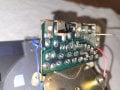
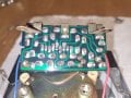
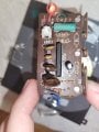
Tachometer suddenly died, wondering if the chip is likely still operational.

Thread Starter

Stuntman225

Joined Apr 28, 2026
76
Check all solder joints, it is common for them to fracture. In pics, the one at the zener anode (by M+ red wire) looks busted.
I did a schematic for these tachs, helping a guy fix it in his Supra I think. Would have to dig for it.
I thought it was like an 8V zener regulator that powers everything.
Strange the cap had enough current to pop the top.

edit:
Can you post clear pics of the underside of the PCB? I can draw a quick schematic. The one I did is for a Honda with Toshiba V/F converter IC similar to this one. There, the zener is for transient protection 20V part.
When it doesn't work - is it reading low or stuck or what?
I would also look if anything got into the meter movement. May have been a spill on the dashboard that dribbled in.
The gauge stays stuck at 0 rpm. I was driving and the needle dropped to 0 and has stayed there. The "motor" is still intact I believe, it reads 160ohms at the pins.
I started working on a schematic when the board was still attached to the tach, so I believe that all of the wires are in the right places, but i'm not a 100% sure. It's in the zip file somewhere.
 

Attachments

Thread Starter

Stuntman225

Joined Apr 28, 2026
76
The zener diode is reading 8678 ohms one direction, and jumps between 22k ohms to 3000 ohms on the other side as i read it.
 

bassbindevil

Joined Jan 23, 2014
924
that gunk looks like a deliberate squirt of goo which has become brittle with age.

Check for continuity between the board and the terminals; the rivets look like a dissimilar metal and maybe there's enough corrosion or tarnishing to break the connection. I've seen that with a DC power jack that needed a whack with a hammer and punch to fix it. Also, verify all the connections back to where it gets power, ground, and the ignition signal.

If all else fails, National Semiconductor makes or made a chip for analog tachs, LM2907 and LM2917 (one of 'em has a built-in zener or something).
 

Thread Starter

Stuntman225

Joined Apr 28, 2026
76
The very first thing that I would have done would be to verify that the correct voltage is supplied, as well as the common connection and the ignition system pulses. It makes sense to first check the external portions. It could even be that constantly moving connection in the meter. I recall most of those in-cluster tachs cover about 270 degrees of rotation.
The first three times that my aftermarket tachometer suddenly quit working were caused by the wiring to the spark coil failing. Then I finally did a better instakllation with adequate anchor points. No more failures. That was many long years ago. Now the cars come with a tach already.Driven by the ECU.
I have verified that I'm getting coil signal to the tach pin with my oscilloscope. Also, the "motor" inside the tach still looks perfect, and has 160 ohms across it.
 
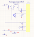
I drew a schematic. Thank you for posting the pictures. I could not see all the part values but it's enough to figure out the circuit a little. Let me know if you spot errors.
Toshiba Frequency to Voltage Converter IC datasheets are hard to find. In the Honda it was a T2295A IC, similar but a little different. Could not find any T2621 data.
I would say power is pin 9 maybe protected/regulated by the zener, and at pin 3 with the leaky cap.
The pickoff from the coil seems a bit low resistance at 3.3k because it sees at least 400V spikes across it and other tachs use a bigger value part there to not load the coil down.
The two larger film caps I would check as well for shorts, if the leak affected them. Could not read them but a crack in the plastic or something would make them give trouble, especially the larger one at pin 1.
edit: updated part values

Toyota 4Runner Tach schematic rev1.PNG
 
Last edited:

Jerry-Hat-Trick

Joined Aug 31, 2022
839
Is the meter really just an analog (moving coil) meter, maybe with a resistor in series to turn it from an ammeter to a voltmeter? And can you disconnect the meter to check if it still works? If so, I'd be tempted to build replacement electronics from scratch using something like a LM2917 frequency to voltage converter. Or digitally with a small processor like an ATtiny85 with PWM output.
 

Thread Starter

Stuntman225

Joined Apr 28, 2026
76
I drew a schematic. Thank you for posting the pictures. I could not see all the part values but it's enough to figure out the circuit a little. Let me know if you spot errors.
Toshiba Frequency to Voltage Converter IC datasheets are hard to find. In the Honda it was a T2295A IC, similar but a little different. Could not find any T2621 data.
I would say power is pin 9 maybe protected/regulated by the zener, and at pin 3 with the leaky cap.
The pickoff from the coil seems a bit low resistance at 3.3k because it sees at least 400V spikes across it and other tachs use a bigger value part there to not load the coil down.
The two larger film caps I would check as well for shorts, if the leak affected them. Could not read them but a crack in the plastic or something would make them give trouble, especially the larger one at pin 1.
Thanks, this is a lot easier to read than whatever i came up with. I did make a few changes to the component values in ms paint, but the of the traces seem to follow perfectly.Toyota 4Runner Tach schematic draft.PNG
 

Thread Starter

Stuntman225

Joined Apr 28, 2026
76
Is the meter really just an analog (moving coil) meter, maybe with a resistor in series to turn it from an ammeter to a voltmeter? And can you disconnect the meter to check if it still works? If so, I'd be tempted to build replacement electronics from scratch using something like a LM2917 frequency to voltage converter. Or digitally with a small processor like an ATtiny85 with PWM output.
The gauge has 2 clock springs that current passes though to move the needle. The springs aren't broken as i can see them flex as I turn the needle by hand. I could build a new logic board, but I'm hoping it's easy to fix this board, and I don't have great experience with logic circuits to design a new one without damaging the needle mechanism.
 

Jerry-Hat-Trick

Joined Aug 31, 2022
839
The gauge has 2 clock springs that current passes though to move the needle. The springs aren't broken as i can see them flex as I turn the needle by hand. I could build a new logic board, but I'm hoping it's easy to fix this board, and I don't have great experience with logic circuits to design a new one without damaging the needle mechanism.
I’m sure someone here could sketch you a schematic which could be built on strip board in case you can’t fix it. I still think it would be worth trying to test the meter on its own - knowing what current or voltage moves it to full scale would be useful for a simple replacement design. Hope you can fix it but I’m concerned from reading this thread that the problem may be the obsolete IC
 
OK corrected the schematic above in reply #25.

I would look closely at the 12k, it has some brown goop on it. Next to it, the big film cap(s) got the slime as well.
Scrape off that brown goop between the parts along the board bottom edge - it might be carbonized/conductive.
If the 12k or the 683K cap shorted, the tach IC would get no input signal and read zero. See if the spill attacked those parts.
I use a Q-tip and IPA to clean PC boards, but we're not sure what was leaked onto the board, if it's acidic or caustic sometimes you need to neutralize that first.

I was fixing a laptop that smelled of really nice hot chocolate inside, a bit puzzled then I find she'd spilled her morning hot chocolate in the keyboard and a little flood happened. Not a virus problem lol.
 

Thread Starter

Stuntman225

Joined Apr 28, 2026
76
I've tried to clean off as much of the crusties as possible, and like what bassbindevil was saying it seems like a potting material. I broke off a few small pieces to measure with my multimeter and it is non conductive.
I'm kinda at a loss on where to go from here, other than try and replace all of the caps and hope it works, or design a new logic board based on the LM2917 chip. All new caps would cost around $15, and I'm not sure that the caps are what's broken. I'm going to try and reflow the solder, but i don't believe it will work.
 
If you power up the board and measure the DCV on the IC pins (engine off), post the voltage readings here and that should help figure out if the IC being good/bad.
I'm a bit confused- it was working but not above 3,000RPM then you replaced the leaky cap and now it's dead, reads zero? Like a new problem showed up? I wonder if it's a bad connection, those aluminium rivets are gross.


If the IC is bad, some possibilities:
Auto wrecking yard and find another tach. The same (car maker) year same IC usually was used in many models.
Or you could make a small PCB that fits in place of the Toshiba SIP IC, using a decent IC like LM2917 is great, available in SOIC-14 package which is small (DIP is obsolete). The IC is closest to the Toshiba F/V IC's used in cars and motorcycles like T2295A, T2621, T2685A etc.
On the Internet there are a zillion car tach circuits and most of them are garbage, or a copied garbage circuit.

For a custom tach circuit you'd need to know the meter movement's full-scale current. A test with a limiting resistor and a variable power supply or an AA battery could be done. Example, 1.5V AA battery and 140 ohm resistor gives about 5mA including meter coil (you call it motor) is 160 ohms, applied at the red/blue wires and see what it reads. You could use a potentiometer but careful not to peg the meter hard i.e. always have say 100-150ohms in series to limit test current.
 

Thread Starter

Stuntman225

Joined Apr 28, 2026
76
If you power up the board and measure the DCV on the IC pins (engine off), post the voltage readings here and that should help figure out if the IC being good/bad.
I'm a bit confused- it was working but not above 3,000RPM then you replaced the leaky cap and now it's dead, reads zero? Like a new problem showed up? I wonder if it's a bad connection, those aluminium rivets are gross.
Sorry about the confusion. Last Saturday I was driving with the engine around 3000 RPM, and then all of a sudden the tach needle bounced like it usually does when i shut the engine off, and then stayed at zero, all while while i was still driving. I have since changed the 33uf cap and reflowed the solder joints to try and to make the needle move again but it has not moved from 0 since.
The aluminum rivets just hold the screw posts on, they are properly attached with solder to the board.
If the IC is bad, some possibilities:
Auto wrecking yard and find another tach. The same (car maker) year same IC usually was used in many models.
Or you could make a small PCB that fits in place of the Toshiba SIP IC, using a decent IC like LM2917 is great, available in SOIC-14 package which is small (DIP is obsolete). The IC is closest to the Toshiba F/V IC's used in cars and motorcycles like T2295A, T2621, T2685A etc.
On the Internet there are a zillion car tach circuits and most of them are garbage, or a copied garbage circuit.
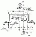
I don't have a cheap way to get a old Toyota tach without spending $100s. I'm planning to try and make a board for this circuit that i found for the LM2917M.
LM2917-Automotive-Tachometer.gif
For a custom tach circuit you'd need to know the meter movement's full-scale current. A test with a limiting resistor and a variable power supply or an AA battery could be done. Example, 1.5V AA battery and 140 ohm resistor gives about 5mA including meter coil (you call it motor) is 160 ohms, applied at the red/blue wires and see what it reads. You could use a potentiometer but careful not to peg the meter hard i.e. always have say 100-150ohms in series to limit test current.
I'll make sure to test the range of motion. So does the coil require current or voltage to move? I have a cheap signal generator that I can use to put out a max of 3 volts.
 

Jerry-Hat-Trick

Joined Aug 31, 2022
839
Typically an analog meter is driven by current. Note that the one shown in your latest schematic is marked as being 10mA for full scale deflection (FSD) which is fairly typical. It’ll have a very small resistance which can effectively be ignored. The way to turn it into a voltmeter is to have a resistor in series with it. Note the 500R calibration potentiometer.

I’d start with a 1K resistor in series and apply your 3V. That will send a current of about 3mA. Hopefully it’ll deflect enough for you to guess the FSD current and try a lower value resistor to check full scale deflection

Be careful not to try too low a resistor value as you could break the meter with 3V directly across it.

DIP versions of the LM2917 are certainly available in the UK - maybe obsolete but still out there
 
Last edited:
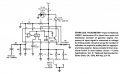
I find that old 1976 app note AN-162/SNAA088 tach schematic has some errors in it, 50 years later lol.

LM2917 pin 12 shows a couple orphaned 10k resistors that do nothing and the comparator (-) input is grounded as if a LM2907.
I thought it's a cut'n paste error - the 10k's were a divider to bias up the (-) input to 3.8V (7.56V/2).
Here the -ve input voltage to toggle the hysteresis flip-flop comes from the AC-coupling input cap, a scheme which I have not tried. If that circuit works, then an LM2907 could be used.
The app note explantion of the IC's input amp circuit seems fairly difficult to follow.
I'm stuck wondering if the (+) input needs to go -ve voltage like a transformer or reluctor pickup would do, for the LM2907 circuit, which does not work for a tach circuit, unless AC-coupled.
LM2917 tach app note cct enh.jpg
 

Thread Starter

Stuntman225

Joined Apr 28, 2026
76
I found this article where someone used the LM2917 to make their own circuit.
http://www.dummett.net/ime/website/ime/a2z/electronic_tacho_driver_using_LM2917N.html
Does his circuit make more sense than the last? I actually wouldn't be surprised if my other schematic was for points, rather than for a VR sensor. I'm running around the internet right now to try and find reasonable looking schematics.
Also, is there any benefit to using the LM2917 over the LM2907 other than it's size?
 
Top