Tachometer suddenly died, wondering if the chip is likely still operational.

Thread Starter

Stuntman225

Joined Apr 28, 2026
41
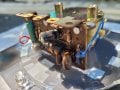
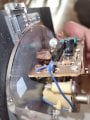
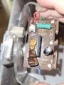
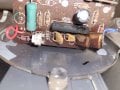
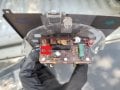
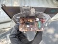
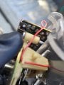
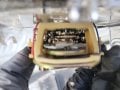
Hello, the tachometer in my 1st gen 4runner suddenly died, and I pulled it open to look inside to see if it was damaged inside. Upon looking inside, I saw rust on some of the traces and what i believe is capacitor fluid on the chip and a capacitor. The chip doesn't have any visible damage except for the crusties in the picture or rust on the pins underneath. I'm wondering if the chip is likely damaged from current passing though it without the needle moving or the fluid resting on it as I don't really want to reverse engineer the board if brains are dead. There is also a resistor under one of the upper left capacitors that is quite toasty looking, but I forgot to take a picture of it.
Before this all happened, the tach was also inaccurate past 3000 RPM.
I have checked grounds, coil signal, and power to the tachometer, and all are good.
Thanks!
 

Attachments

Reloadron

Joined Jan 15, 2015
7,882
Scrub the board down and obviously if you see leaking capacitors replace them. Less a detailed schematic it's hard to make any further suggestions..

Ron
 

schmitt trigger

Joined Jul 12, 2010
2,058
What I wanted to say in my previous post;
Difficult to see from the photo, but it does appear that the magic smoke did escape from the IC. At least some.
 

Thread Starter

Stuntman225

Joined Apr 28, 2026
41
What I wanted to say in my previous post;
Difficult to see from the photo, but it does appear that the magic smoke did escape from the IC. At least some.
I should have taken a different angle of the chip, but the casing of the chip looks fine excluding the flaky electrolyte on top of it. I'm more worried about if the chip could have been damaged because it wasn't getting the right voltages as the capacitor died.

I'll try and get better pictures tomorrow.
 

MisterBill2

Joined Jan 23, 2018
27,385
When an electrolytic capacitor pukes outthe side. IT IS FAILED. So replace that capacitor with one of the same value but a higher voltage rating, and a better brand. I have not trusted that light-blue brand of polarized capacitors for many years. No need to replace the other caps. BUT inspect the restof the assembly to see if there is a shoted circuit hiding.
 

MikeA

Joined Jan 20, 2013
446
It seems as if someone might have spilled something onto the board a long time ago.
Inside the instrument cluster? That seems unlikely. It doesn't look like it came from the capacitor either. It looks like the remains of some bug/nest/spider that decomposed in that spot. But that doesn't mean the capacitor didn't dry out in 37+ years in a harsh environment and needs to be replaced.
 

Thread Starter

Stuntman225

Joined Apr 28, 2026
41
I managed to find a 33uf 16v cap to replace the old 33uf 25v cap with and the tach still remains broken. I was planning to use the 16v cap just for testing as the truck is a 12v system and I don't have any 33uf 25v caps. Should I go though and buy all new caps or just replace my 16v cap with a proper 25v?
 

Reloadron

Joined Jan 15, 2015
7,882
I would start by replacing the obvious faulty components like leaking caps. You know those need replaced. The 33 uF 16 volt cap should be fine for test purposes.

Ron
 

MikeA

Joined Jan 20, 2013
446
as the truck is a 12v system
Doesn't mean everything on that circuit board is running on 12v. A tachometer in a 1980's vehicle almost certainly ties into the ignition system, so it's actually counting very high voltage pulses from the distributor.

Looking at the picture more, I'm almost 100% certain it's not the capacitor leaking. It would have had to leak up against gravity to make it onto the black IC.
 

gaber2611

Joined Mar 14, 2013
324
I should have taken a different angle of the chip, but the casing of the chip looks fine excluding the flaky electrolyte on top of it. I'm more worried about if the chip could have been damaged because it wasn't getting the right voltages as the capacitor died.

I'll try and get better pictures tomorrow.
Is there any short circuit between any two pins of the IC?,
On doide mode, try to test ic pins if there is any short,
Also I see seiner diode, is it OK?, have you tested?
 

Thread Starter

Stuntman225

Joined Apr 28, 2026
41
Is there any short circuit between any two pins of the IC?,
On doide mode, try to test ic pins if there is any short,
Also I see seiner diode, is it OK?, have you tested?
I haven't checked the ic pins for shorts yet.
How would I go about testing the zener diode? I know it's not a diode type that I'm used to seeing.
 

gaber2611

Joined Mar 14, 2013
324
Just like the diode test, one direction should
I haven't checked the ic pins for shorts yet.
How would I go about testing the zener diode? I know it's not a diode type that I'm used to seeing.
give 0.6-0.7 other direction nothing, in board test will be different, you can one pin desolder and test on diode mode
 

MisterBill2

Joined Jan 23, 2018
27,385
The very first thing that I would have done would be to verify that the correct voltage is supplied, as well as the common connection and the ignition system pulses. It makes sense to first check the external portions. It could even be that constantly moving connection in the meter. I recall most of those in-cluster tachs cover about 270 degrees of rotation.
The first three times that my aftermarket tachometer suddenly quit working were caused by the wiring to the spark coil failing. Then I finally did a better instakllation with adequate anchor points. No more failures. That was many long years ago. Now the cars come with a tach already.Driven by the ECU.
 
Last edited:
Check all solder joints, it is common for them to fracture. In pics, the one at the zener anode (by M+ red wire) looks busted.
I did a schematic for these tachs, helping a guy fix it in his Supra I think. Would have to dig for it.
I thought it was like an 8V zener regulator that powers everything.
Strange the cap had enough current to pop the top.

edit:
Can you post clear pics of the underside of the PCB? I can draw a quick schematic. The one I did is for a Honda with Toshiba V/F converter IC similar to this one. There, the zener is for transient protection 20V part.
When it doesn't work - is it reading low or stuck or what?
I would also look if anything got into the meter movement. May have been a spill on the dashboard that dribbled in.
 
Last edited:

Homebrew1964

Joined Nov 22, 2024
164
If it were my project i would replace the capacitor and reinstall the board before a test run, the capacitor has most likely leaked onto the IC but that wouldn't damage the IC or cause a short between the pins.
 
Top