Tachometer circuit help (self-solved)

Thread Starter

metermannd

Joined Oct 25, 2020
472
When I was looking at some prints to see what assemblies to chase down for my little reverse-engineering project, I realized one assembly would likely be past unobtainium at this point.

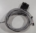
This is a small circuit board that serves as the tach for the motor control. Although my company assembled the motor control, we did not assemble the tach (but we had PCB blanks for it!) I seem to remember the board was potted as well.
nsaspook: The number I have at hand for this tach assembly is 902828-001.

Given how scarce some of the components for the system have become, I have no doubt that when these units were being broken up for scrap or reselling spare parts, the tach was probably dismissed as a cable and sold for copper.

So, I would like to just pull together something that would be functionally identical for the purpose of illustrating how the system worked.

What I DO remember is the board had an optical fork for interfacing with the code wheel, which was on the turntable shaft itself. According to a print I got a while back, that wheel has 360 slots, and the assembly description suggests that it had a 14' cable (spanning from the bottom of the unit to the top plus some slack).

The attached is just something I pulled together (cut and paste from another schematic I had plus some quick tweaks).

What I would like is a bit of help from the brain trust to help me clean up the design to something that would have been 'period appropriate' to the early 1980s. (I don't ask for much do I?)

This circuit had a relative minimum of parts besides the optical fork and a single 8-pin IC...tach.png
 

Thread Starter

metermannd

Joined Oct 25, 2020
472
Managed to scare up a picture of what the assembled tach looks like...
I was right that this gets potted - and that doesn't look like the soft silicone stuff either.
 

Attachments

MaxHeadRoom

Joined Jul 18, 2013
30,558
BTW, schematics signals, usually go from left to right,
Looks like a Kicad pgm used, the power flag indication is a little unconventional?
 

Thread Starter

metermannd

Joined Oct 25, 2020
472
Correct that it was drawn in KiCAD, and this was just something quick I ripped out of another in my files... after I finish drawing a few more schematics, I need to go back and optimize several of them - I think I had this one 'backwards' to better fit the available space on that diagram.

Some of my schematics have the power flags like so, and others have the power flag all by themselves attached to the corresponding buses.
 

MisterBill2

Joined Jan 23, 2018
27,164
The circuit shown is entirely reasonable, it will deliver a good square wave to whatever that 6 pin item is. But it is not a tachometer, it is a pickup device to feed a tachometer, 360 pulses per revolution.
 

Thread Starter

metermannd

Joined Oct 25, 2020
472
Here's that circuit continuing beyond the 6-pin connector...

The Tach signal gets passed back into the interface board (where it passes through a VN10KM buffer stage), then on to the CPU board, terminating at one of the 8253 timer inputs.

The Speed signal runs to the Clk input of the lowest of four cascaded 14522 counters, as well as the section below it.

Lastly, the _RNG signal goes back to the interface board to indicate that the turntable is currently in motion.

msc logic.png
 

MisterBill2

Joined Jan 23, 2018
27,164
I do not see anything except pulses in any of the outputs. So this system feeds a pulse time counter calibrated in speed??? Or have I mussed something important???
 

Thread Starter

metermannd

Joined Oct 25, 2020
472
MisterBill2: I see your point regarding the name of the circuit, but I have a copy of the BOM for the assembly this went into, and the module shown in post 2 is listed as "Assy, Tach, MSC, 14'" on the bill of materials I have at hand, which is why I refer to it as such.

sghioto: No I haven't, actually. As I said, I have been approaching this from a "How would they have done it?" perspective since the completed assembly is potted and not possible to do a nondestructive analysis (if these weren't nearly unobtainium, I would have bought 2, of course!).

Even so, the motor control this tach assembly was paired with has three TO-220 IGBTs that were a notorious weak point back in the day, so much so, when the supply through official channels completely dried up in the mid-'90s, the company did a respin of the board to use two TO-247 IGBTs instead. I don't have one of the DC motors this would have been used with either.

panicmode: Oops! :)

What happened was the diagram from which I ripped that circuit block used a reflective sensor and I changed the symbol to an optical fork without paying attention to the polarity of the transistor.

Good catch, thank you. I swapped the connections around for now. I'll go for a more permanent fix soon.

As for the part values, like I said, those were the component values in the original circuit. I've adjusted the LED resistor and I actually also changed the 1% resistor values to the closest 'standard' 5% resistor values as well.

Would the LM2903 have been a standard comparator back in the early '80s?
 

Thread Starter

metermannd

Joined Oct 25, 2020
472
MisterBill2: If it helps, I've attached the full schematic of the board that tach / encoder plugs into... it's still somewhat a work in progress. I'm not really satisfied with the right-hand portion.

Edit: I should add, this is the 'cold' side of the motor control. If the schematic of the 'hot' side board is desired, I can post.
 

Attachments

Last edited:

MisterBill2

Joined Jan 23, 2018
27,164
Previously available were the LM2900 and LM2902, both QUAD comparators in the 14 pin DIP package. Very similar characteristics, I think, but a totally different package. NOT plug-interchangable.

And it is not clear to me just what the circuit does, other than it appears to be a closed loop speed control/position control system.
 

Thread Starter

metermannd

Joined Oct 25, 2020
472
Were there other alternatives before the LM29xx? I did have access to a PCB blank at one point many years ago and seem to recall the IC was 8 pins. LM393?

This was out of a system that processed semiconductor wafers to treat them with various chemicals at different stages. The main process console had a tub into which the wafer carriers were placed. The tub was then spun at various speeds while the chemicals were sprayed onto the wafers. So, yes, closed-loop speed control. :)
 

MisterBill2

Joined Jan 23, 2018
27,164
But the bottom should be the"negative" or the common side, not "GND". Sorry to be so picky, but the negative side of a supply does not need to be connected to "ground".
 

Thread Starter

metermannd

Joined Oct 25, 2020
472
I now have the tach in post #2 in hand - there are four conductors: +12, Tach, Gnd, shield.

The opto-interrupter is a Honeywell HOA0971-T51.
This coming week, I'll put this under the X-ray at work and see if I can get something that we can at least use to reason out the overall circuit arrangement. The sensor isn't that big either; 1.75 x 1.75 x 0.5 (not counting sensor height).
 
Last edited:

MisterBill2

Joined Jan 23, 2018
27,164
I have not heard the optical interrupter called "a fork" before. So it took a few moments to figure out what it was referencing. Those devices are still available although the package may vary a bit.
Unfortunately, the main failure modes were breakage from careless operators.
 
Top