Tachometer suddenly died, wondering if the chip is likely still operational.

Jerry-Hat-Trick

Joined Aug 31, 2022
840
I’m fairly sure the ATtiny85 with a clock speed of 8MHz will do the job. The signal from the distributor will cause an interrupt and at 600 RPM that’s 50mS between pulses, 5mS at 6000 RPM. After each pulse, probably 2mS debounce time. Use just integer arithmetic. Possibly at higher RPM you could choose not to update the output every pulse. The PWM resolution is 8 bit, so storing 256 values in flash would avoid any need for interpolation. Reading from flash memory takes 3 clock cycles.

My suggestion is to build a minimal version of the hardware to test. Leave out the opto and drive the ATtiny directly from an Arduino UNO. Use a pot to adjust the frequency of 1mS pulses on the UNO and monitor with serial.print. Assume that the meter response is linear so you can test what frequencies actually move the meter to multiples of 100 RPM. This gives you the information you need to populate the lookup table
 

Thread Starter

Stuntman225

Joined Apr 28, 2026
76
I have ordered all of the parts to build a tachometer board with the ATtiny85. I'll update when everything to test shows up.
 

Jerry-Hat-Trick

Joined Aug 31, 2022
840
Just to say, I've now wriiten code for the Arduino UNO which simulates the coil signal by going negative for 1ms then back to positive for up to 8000 RPM adjusted with a potentiometer and fed this into an ATtiny85 driving a proportional PWM quasi analog signal to change the brihtness of an LED. I don't have an analog meter to test. I confess to using ChatGPT to help write the code both for the UNO and for the ATtiny - quick and dirty - and I've yet to understand it completely but it works for now....

Next step is to create a calibration array of values which can take the measured RPM and adjust the PWM to display the correct meter reading. My guess is that a value for each 1000 RPM with linear interpolation will be sufficiently accurate and this could be done without the need for using FLASH memory.
 

Thread Starter

Stuntman225

Joined Apr 28, 2026
76
Just to say, I've now wriiten code for the Arduino UNO which simulates the coil signal by going negative for 1ms then back to positive for up to 8000 RPM adjusted with a potentiometer and fed this into an ATtiny85 driving a proportional PWM quasi analog signal to change the brihtness of an LED. I don't have an analog meter to test. I confess to using ChatGPT to help write the code both for the UNO and for the ATtiny - quick and dirty - and I've yet to understand it completely but it works for now....

Next step is to create a calibration array of values which can take the measured RPM and adjust the PWM to display the correct meter reading. My guess is that a value for each 1000 RPM with linear interpolation will be sufficiently accurate and this could be done without the need for using FLASH memory.
If you could make it work before me, that would be awesome. I'm currently trying me best to understand how C++ works and code a working prototype.
I'll be making a new thread on the Arduino forum really soon about the coding.

Edit: Coding thread: https://forum.arduino.cc/t/writing-code-for-an-analogue-tachometer-powered-by-attiny85/1443125
 
Last edited:

Jerry-Hat-Trick

Joined Aug 31, 2022
840
I’ve taken a real quick look at the thread on the Arduino forum. I recommend assuming it’s linear for the first code to test. Even if code compiles doesn’t mean it’ll work as expected! I could post my code for you but I’m not exactly proud of it
 

Thread Starter

Stuntman225

Joined Apr 28, 2026
76
I’ve taken a real quick look at the thread on the Arduino forum. I recommend assuming it’s linear for the first code to test. Even if code compiles doesn’t mean it’ll work as expected! I could post my code for you but I’m not exactly proud of it
I'm working on making lookup tables in the background, i will be assuming it's travel is linear until the code works pretty much flawlessly. What that means i don't know, but I'll find out.
 

Jerry-Hat-Trick

Joined Aug 31, 2022
840
I'm working on making lookup tables in the background, i will be assuming it's travel is linear until the code works pretty much flawlessly. What that means i don't know, but I'll find out.
Apart from checking everything works, the main purpose of using the Arduino UNO to test the ATtiny is doing what it’s supposed to do is to have the UNO code print the RPM on the computer screen and adjust the potentiometer to find out what actual RPM will display, for example, 3000 RPM on the meter. Let’s suppose the UNO has to generate 3300 RPM to display 3000 on the meter. In this case, in the Lookup table, when the ATtiny actually sees 3000 RPM it has to drive the meter as if it were 3300 RPM. I’d do this for each thousand RPM to have an array which can be interpolated. I’d certainly leave writing the code for this until after the basic code is shown to function correctly. The code should also include a correction for changes in battery voltage, which should be linear but if it proves to be more complicated your idea for a voltage regulator would sort that out. I’d use maybe 9V which would mean a smaller value series resistor than the suggested 390R
 

Thread Starter

Stuntman225

Joined Apr 28, 2026
76
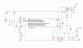
Here's the next version of the Attiny85 circuit. It has a 20MHz crystal oscillator, flyback diode, input diode, and potentiometer. It also has a 100nF cap between the power and ground pins of the Attiny85.
Attiny85 tach board v1.png
 
Last edited:
Neater than my sketch! The diode should probably be just across the meter rather than the meter in series with the resistor but it may not matter, the inductance of the meter is probably pretty small. Adding a 20MHz crystal certainly gives you faster processing and timing accuracy but I question the need for it - you are already getting a big improvement in accuracy with the linearization. I’m looking forward to seeing this working, please keep posting updates.
 
I do not see the pull up resistor for the optocoupler output.
Jerry did use a 4k7.

Bertus
Thanks for spotting this. I'm actually not sure if it's necessary, I think you can enable an internal pullup in the code with "pinMode(INPUT_PULLUP)" although I typically prefer an external resistor
 
Just noticed, the resistive divider to measure battery voltage is missing from the latest schematic. This is really necessary, or possibly a 9V regulated supply to the meter (with a reduced value of R5). Probably should have a 100nF capacitor across the 5K6 resistor, close to the ATtiny. It may be a bit noisy so worth taking the average of the last say 16 samples as the actual voltage won't change too quickly.
 

Thread Starter

Stuntman225

Joined Apr 28, 2026
76
Just noticed, the resistive divider to measure battery voltage is missing from the latest schematic. This is really necessary, or possibly a 9V regulated supply to the meter (with a reduced value of R5). Probably should have a 100nF capacitor across the 5K6 resistor, close to the ATtiny. It may be a bit noisy so worth taking the average of the last say 16 samples as the actual voltage won't change too quickly.
I forgot to mention that i moved the meter's input power to the 5v rail. Some people on the Arduino forum said to attach the meter to the 5v rail so extra coding and calculations weren't necessary.
 
I forgot to mention that i moved the meter's input power to the 5v rail. Some people on the Arduino forum said to attach the meter to the 5v rail so extra coding and calculations weren't necessary.
Not sure I agree 100% but it should work. Don’t forget to reduce the series resistor values! I should have looked more carefully at your schematic, I see now that you are using the 5V
 

Thread Starter

Stuntman225

Joined Apr 28, 2026
76
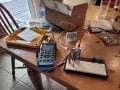
My parts showed up, so testing will commence once i can figure out why my Uno isn't doing anything. I bought a cheap mA gauge so i can verify that i won't blow up my tachometer's coil with the Uno.20260511_132522.jpg
 

Thread Starter

Stuntman225

Joined Apr 28, 2026
76
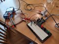
One hurdle passed, everything working for the first time. The Uno Q that i started testing with runs python natively, which I didn't know. (I was able to borrow the Q for free, that's why I was using it) After buying a Elegoo Uno R3, my code works somewhat. The gauge operates backwards, when rpm increases the mA output goes lower, and when rpm decreases mA output goes higher. I just need to get the right equations, and every thing should work without the interpolation function. 20260514_164345.jpg
 
Great progress! You've probably worked out already, but I think you need to convert from Time Between Pulses (TBP) in microseconds to 96,000/TBP for the PWM value you need if the meter movement is linear.
 
You've probably worked out already, but I think you need to convert from Time Between Pulses (TBP) in microseconds to 96,000/TBP for the PWM value you need if the meter movement is linear.
My mistake, it should be 960,000/TBP for direct conversion to a linear PWM value. 30,000,000/TBP to convert to RPM. By taking RPM/1000 you have the lookup table number. Also read the next number - the difference times the remainder of RPM/1000 all divided by 1000 gives the extra PWM to be added. Not that well explianed - hope it's clear....

You are using a 50mA FSD meter for testing for which you will need a series resistor of 100R instead of 330R + 50R trimpot. For the 30mA, probably 100R plus 50R trimpot to make a total around 166R

I'm looking forward to seeing this working with your actual meter and the spark signal. I'm thinking of using an ATtiny84 which has more I/O to drive an MX5 (Miata) air core tachometer which is more likely to be linear - it needs 4 x I/O and a sine/cosine lookup table
 

Thread Starter

Stuntman225

Joined Apr 28, 2026
76
I have achieved greatness! I got meter moving accurately across it's path with an Uno R3. The needle is slightly sticking, but hopefully some light oil will fix that. All that's really left is to see if my code runs on a ATtiny85.
 
Top