Tachometer suddenly died, wondering if the chip is likely still operational.

Thread Starter

Stuntman225

Joined Apr 28, 2026
76
I found this schematic for a tach filter that works fairly well. Unfortunately, I only have .20uf caps and 250pf caps, but the circuit worked well regardless.
Hei tach filter.jpgThe opto behaved fairly well, but still had a few hiccups. Orange is opto in, Blue is opto out.img_20.jpgimg_21.jpg
I'm debating on using a zener diode like mccrae did to limit voltage going to the schmitt, but i have to wait a few days to get them. (It's hard to plan for everything without spending a million dollars).
This is what the schmitt did with the opto's output when it was behaving.
img_22.jpg
 
You haven’t mentioned the nature of the “hiccups” - I wonder if your code includes ignoring any input for 2mS after it sees a valid input to avoid being triggered by ringing. My code also only recognizes an input if it sees 3 successive inputs in a fast loop but that may not be necessary or even advisable.
 

Thread Starter

Stuntman225

Joined Apr 28, 2026
76
You haven’t mentioned the nature of the “hiccups” - I wonder if your code includes ignoring any input for 2mS after it sees a valid input to avoid being triggered by ringing. My code also only recognizes an input if it sees 3 successive inputs in a fast loop but that may not be necessary or even advisable.
The hiccups are when the opto seems to forget how to function, either staying on too much or not turning off.
 

Thread Starter

Stuntman225

Joined Apr 28, 2026
76
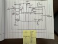
I found a circuit that seems to work pretty good. Putting only resistors before the optocoupler makes it operate fine, so i put resistors between the attiny, schmitt, and opto to tune their on and off points.
My code only seems to work up to 3000 rpm right now, but I can fix that.Screenshot 2026-06-09 084302.png
 

Attachments

Thread Starter

Stuntman225

Joined Apr 28, 2026
76
Well, I'm slightly silly. While cleaning some things up today, I found my optoisolator module that i bought for another project, and it outputs a perfect (or at least seemingly perfect) signal that i can send to the Attiny. https://diyautotune.com/products/axm-110?_pos=1&_sid=c2602777c&_ss=r
I'm going to try and use it with Attiny part of the circuit tomorrow, and if it works i'll try and copy it's circuit to put on my circuit board. I trust an engineered product's circuit slightly more than my attempts.
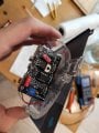
It's guts for those interested. (The opto is one of these https://www.vishay.com/docs/83725/4n25.pdf)20260609_163305.jpg
 
Okay, the 4N25 opto gives you access to the base of the photo transistor which may well be better! Probably a resistor from the base pin to ground will help it turn off cleanly. A large value like 100K to start with?
 

Thread Starter

Stuntman225

Joined Apr 28, 2026
76
Okay, the 4N25 opto gives you access to the base of the photo transistor which may well be better! Probably a resistor from the base pin to ground will help it turn off cleanly. A large value like 100K to start with?
Maybe? For testing i'm going try and use it in it's current form unmodified.
 

Thread Starter

Stuntman225

Joined Apr 28, 2026
76
Both methods of input filtering for the Attiny seem to work well, so I'm going to get some actual pcbs to do testing and hopefully final assembly on. They will probably take a week or two to arrive, so updates probably won't be for a while.
I did some other testing for filtering the pwm signal going to the meter, and a .1 uf cap across the meter's pins made it react more smoothly.Screenshot 2026-06-12 201058.pngScreenshot 2026-06-12 201137.png
 
Last edited:
Great work! I'm still concerned that your schematic shows single resistors connected in parallel to the coil. If they are 200V resistors they are seeing way too much voltage - they may survive testing but they probably won't last long in practice. I'd recommend at least two, possibly three in series to spread voltage between them - maybe 4K7 x 3. If the peak voltage is 500V with the parallel resistors as shown, the peak current will be 38mA which the PC817 can handle. Also, to protect the opto LED I'd suggest, as originally drawn, a diode to protect it by making sure the opto doesn't see more than 0.6V in the wrong direction.
 

Thread Starter

Stuntman225

Joined Apr 28, 2026
76
Great work! I'm still concerned that your schematic shows single resistors connected in parallel to the coil. If they are 200V resistors they are seeing way too much voltage - they may survive testing but they probably won't last long in practice. I'd recommend at least two, possibly three in series to spread voltage between them - maybe 4K7 x 3. If the peak voltage is 500V with the parallel resistors as shown, the peak current will be 38mA which the PC817 can handle. Also, to protect the opto LED I'd suggest, as originally drawn, a diode to protect it by making sure the opto doesn't see more than 0.6V in the wrong direction.
If the resistors die because of over voltage, I'll just buy some ones rated for a higher voltage. I didn't think about reverse voltage protection for the opto, I'll try and stuff a diode on the board before I order.
 
Last edited:

Thread Starter

Stuntman225

Joined Apr 28, 2026
76
I got it installed and tested today, and it works great! :) The one problem is that either the needle is sticky and doesn't move as well as it should, or the attiny's 255 different pwm outputs don't provide enough fine adjustment for the low rpms. I'm going to try and make a GitHub for this project, but it might be a bit.
I actually learned how to write code, and the program that i wrote is the one that's in use right now. Instead of waiting for a pulse of a certain length, it just makes sure that the income signal stayed Low off a set amount of time before doing calculations.
20260626_171238.jpg
 

Attachments

Very nicely done! I'm delighted with the way you persisted with getting this processor based solution to work, including code writing. Looking at your arrays, the meter is clearly non-linear so your result will be a big improvement on accuracy :)
 

Thread Starter

Stuntman225

Joined Apr 28, 2026
76
I've been using the tachometer for about a week now, and I'm quite happy with it. There are a few bugs that I need to work out, but I'm happy enough with the project to publish a repository for it.
https://github.com/pauldueck208-blip/22re-Tachometer-Driver-board
Work on the project will be slower now, but I'm going to try and chip away at fixing all of the bugs. If there's anything you would like added in the repo let me know and I'll try and add them. (Pictures will come next time i pull the dash apart).
 
Last edited by a moderator:

hdman90

Joined Jul 22, 2026
2
Hey all,
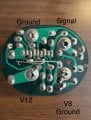
I have the same IC in my tachometer, but my application is for V8's and I6's (the PCB uses an added ground for a V8 application, without it a I6 is default).
Do you think it is possible to utilize @Stuntman225 's solution for my tachometer as well? It'd be nice to match the original application as much as possible to avoid future issues (engine swap or something, who knows!). I'll attach some photos of my stock PCB; I have already replaced the zener diode trying to fix my tachometer without success. My IC is dead as well.
Image (4).jpgImage (3).jpgImage (5).jpg
 

Thread Starter

Stuntman225

Joined Apr 28, 2026
76
If you can change a few settings in code for the needle travel, it should work. What's the red line of the engine?
I don't know how common replacement boards are for your tachometer, but you could probably make I6 board work by soldering a few extra resistors inline with the meter.

If you do plan to go this route, I'll try and help with troubleshooting.
 
Last edited:

hdman90

Joined Jul 22, 2026
2
Movement on this is 120 degrees, 0-6k RPM. Same T2621 IC and clock spring movement.

Replacement boards on this are nonexistent, just like yours.
If I connect my signal generator up to either ground, the tachometer is inoperable regardless. These IC's must have a shelf life, because I've even bought a few replacements from junk yards and those are dead as well.

I'm definitely open to modifying code and hopefully adding the other loop to work for the V8 ground/application as well.
 

Thread Starter

Stuntman225

Joined Apr 28, 2026
76
I'm currently working on a version 2 board that's supposed to be better than my original design, so wait a little bit before designing / ordering pcbs.
I don't know your skill level with electronics, but have you checked to see if the coils that move the needle aren't broken? A signal generator should move the needle, assuming it has enough power. If you're trying to bench test the ic with a signal generator, it would probably have to an output 12v or higher for the ic to see a signal.
 

Thread Starter

Stuntman225

Joined Apr 28, 2026
76
I'm definitely open to modifying code and hopefully adding the other loop to work for the V8 ground/application as well.
Cool, here are the next steps that will need to be done.
  1. Verify that the meter can reach the end of it's travel using 5v.
    1. Using a 5v power source, starting with a 1000 ohm resistor, put a resistor inline with the positive lead to the meter's power lead (Connect the grounds together). Slowly decrease your resistor's value until the needle goes almost exactly to the end of it's range (Usually a bit past the last hash mark on the face ). Save that value to put onto the finished board
  2. Obtain a way to program Attiny85s
    1. I recommend a knock off Uno R3 with genuine Atmel chips with an ISP shield, as an Uno R3 has the same architecture as the Attiny85, so code that runs on the 85 can easily be run on the Uno for testing.
    2. https://www.amazon.com/ELEGOO-Board-ATmega328P-ATMEGA16U2-Compliant/dp/B01EWOE0UU
  3. Make a DXF file or take really good measurements of the original board's size
    1. It's possible to easily import DXF files into PCB software as an outline for the board.
  4. Obtain a way to match Arduino Ide's PWM values to a voltage that matches the set rpm value of the meter (Uno R3).
    1. This table needs to be generated. For my 4runner's meter, when the needle reaches 1000 rpm, the Attiny85's output PWM is at 40.
    2. Using the resistor value obtained above, place it in line with the meter's power, with the Attiny/Arduino switching ground though a transistor. https://www.mouser.com/en/ProductDetail/Diotec-Semiconductor/2N2222A?qs=OlC7AqGiEDmNlRSTGL2dYg==
    3. 1784742583959.png
  5. Figure out what exactly do you want the new board to do.
    1. Shift light, switching cylinder counts, ext.
  6. Show more pictures and tell the make and model of your vehicle :)
 
Last edited:
Top