RS485 Communication Works Without Termination but Fails With 120Ω Termination – What Could Be Wrong?

Thread Starter

akash.kumar123

Joined Jul 20, 2026
33
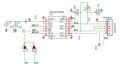
Where is the third wire for the bus? How are the sensors powered? Terminations go on both ends, fail-safe resistors only on one end of the bus. TVS diodes are bidirectional but schematic shows otherwise. What is JP10/17 for?
sensor powere through the 24V from board i am not including that circuit here, termination go on the both end of 120ohm jp10 and 17 for the pull up the B line to the 5 volt on the board
 

MisterBill2

Joined Jan 23, 2018
28,506
IF there has not been any problem with reflections in this particular system installation, (I do not recall any comments about any actual problems) then those resistors may not be required.
To rephrase an old axium: "If it aint broke, it does not need to be fixed" In this specific installation, if there was no problem, why change it???

Consider that there has not been any mention of any problem with this specific installation!!

AND, to quote others: "Just because others do it does not mean that you should do it too". I regard that as usually good advice.
 

Thread Starter

akash.kumar123

Joined Jul 20, 2026
33
If the RS485 functions correctly without that 120 ohms terminating resistor, WHAT IS THE ADVANTAGE anticipated from adding the 120 ohm resistors?? THAT ismy big question.
for long cable length like 200-300m may be the signal distortaion due to the impedance mismatching i connect the 120ohm Resistor
 

Thread Starter

akash.kumar123

Joined Jul 20, 2026
33
What is the line length and the transmission speed of the RS485 bus? At higher transmission speeds or more line length, the TVS diodes between the differential pair will cause problems. Each diode has a junction capacitance of 0.7 nF for the bi-directional or 1 nF for the unipolar type. This will cause signal distortion due to slow rising signal edges.

Furthermore a TVS at this place and with 36 V is absolutely useless. The clamping voltage is somewhere between 40 and 44V and it would only clamp the differential voltage between the signal lines. For a properly installed transmission line, this is almost impossible. So simply remove all your TVS's. Whether an RS485 interface needs some protection depends on the specific use case (cable length, EMC conditions, voltage differences, ...) and has to be decided individually.

The differential voltage you measured is typical for a system with disabled drivers. Usually RS485 receivers accept any voltage difference > 0 V as a logical "1", although most RS485-transceiver datasheets sppecify the receiver output level as "undefined" for an input voltage difference between +0.2 V and -0.2 V. Unless you have several 100 m of cable, the differential voltage with an enabled driver should be well over 1 V measured at the far end of the cable. Do you have oscilloscope screenshots of the signals at the transmitter and receiver while enabling the driver and sending data?
i am using the length up to 300m but at the one port its woring but on the another port its not working and every thing is same
 

MisterBill2

Joined Jan 23, 2018
28,506
If a third point connection is not working then the first step would be a continuity check, followed by a voltage check, and a check for an accidental grounded connection. It may be that the terminating resistors load the signal voltage excessively. But first do a continuity check, followed by a check to see if there is a grounding somewhere.
 

Rf300

Joined Apr 18, 2025
131
jp10 and 17 for the pull up the B line to the 5 volt on the board
This is one of the most common pitfalls when using RS422/485. The standard talks about the "B"-line as the NON-inverting one and the "A"-line as the inverting one. The chip manufacturers, however, mostly use the "B"-pin as the inverting pin and the "A"-pin as the NON-inverting one. So use JP10 and JP17 to connect the "B"-pins to GND. This should give you some DC-bias on your line to avoid unintended receive signals due to EMC noise when the line is not driven by any Transmitter.

Btw.: Are you sure that only one driver at a time is driving the line?

At 300 m cable length, you should use a maximum baud rate of 115.2 kBd unless you use a dedicated ProfiBus cable. Then you can use up to 500 kBd.

And throw away your TVS diodes.
 

Rf300

Joined Apr 18, 2025
131
You need to remove the biasing resistors ... their presence degrades transmission and reception performance
NO! A properly biased RS485 line is much less susceptible to disturbances by EMC, noise, ... than a non-biased. Look at the ProfiBus termination some posts above. This leads to a bias voltage of about 1 V, and this has been proved to be good for harsh industrial environment in 100s of millions installed devices.
 

MisterBill2

Joined Jan 23, 2018
28,506
If the problem is with the 120 ohm terminating resistors, it may work with a GREATER RESISTNCE for terminators. 470 ohms should be an available value, or possibly 500 ohms.
 

drjohsmith

Joined Dec 13, 2021
1,665
can I summarise
your having problems, and changing various resistors , changes the behaviour.
you have around 300m of cable ,
can you look at the data at the transmitters and receiveres ?
are you terminating at both ends of the line or one ?
whats the cable ?
can you share picture of the test setup ?
is this mains or battery powered ?
do you have a scope ?

there could be 1001 reasons why its not working,
unless you can look at the signals, we can but guess what the root cause is
 

cmartinez

Joined Jan 17, 2007
8,881
NO! A properly biased RS485 line is much less susceptible to disturbances by EMC, noise, ... than a non-biased. Look at the ProfiBus termination some posts above. This leads to a bias voltage of about 1 V, and this has been proved to be good for harsh industrial environment in 100s of millions installed devices.
The 120 ohm termination resistors are the bias resistors for this particular chip. Other chips (such as the SN65HVD1176) may require them, but not the one the TS is using. The TS is using the MAX485ESA+T, check its datasheet.
 

drjohsmith

Joined Dec 13, 2021
1,665
The max485 is a bindirectional tranceiver, needs two termination resistors , one at each end of the link, and reqiuires some coorination between the chips to ensure only one transmitter is connected at once,
 

panic mode

Joined Oct 10, 2011
5,424
The 120 ohm termination resistors are the bias resistors for this particular chip. Other chips (such as the SN65HVD1176) may require them, but not the one the TS is using. The TS is using the MAX485ESA+T, check its datasheet.
where exactly does the idea come from that MAX485 does not require terminating resistors?
some of ICs mentioned in same datasheet do feature limited slew rate. Those may work even without terminating resistors. MAX485 is not one of them.
1787676385238.png
 

cmartinez

Joined Jan 17, 2007
8,881
where exactly does the idea come from that MAX485 does not require terminating resistors?
Hello, PM ... I never said that the chip doesn't require terminating resistors. What I said is that it doesn't require the bias resistors (pull-up and pull-down) in his original schematic (R79, R89, R92 and R103).

To clarify, the 120 ohm terminating resistors are required (especially for long cable lengths). Biasing resistors are not.
 

nsaspook

Joined Aug 27, 2009
16,503
Hello, PM ... I never said that the chip doesn't require terminating resistors. What I said is that it doesn't require the bias resistors (pull-up and pull-down) in his original schematic (R79, R89, R92 and R103).
IMO the proper bias resistors should not be causing this problem. I use them all the time in designs with chips that don't require them because I've had issues with random slave devices (Chinese energy meters) I didn't design that are unreliable without them in the circuit.
1787678288871.png


The OP has never posted scope pictures of the failure mode so it's still all quesses.
 
Last edited:

panic mode

Joined Oct 10, 2011
5,424
If the RS485 functions correctly without that 120 ohms terminating resistor, WHAT IS THE ADVANTAGE anticipated from adding the 120 ohm resistors?? THAT ismy big question.
advantage is that bus is properly terminated thus eliminating reflections. any change in bus impedance causes reflections. terminator appears as bus that continues into infinity. properly terminated bus allows high speed communication and communication over short distances where reflected signal is strongest. reflected signal interferes with original and ruins data exchange. in fact reflections come from both ends of the bus and if bus losses are low, both will have multiple reflections. for some low speed applications there are transceivers with limited slew rate. this allows data exchange even if termination is wrong but there are limitations.
 
Top