RS485 Communication Works Without Termination but Fails With 120Ω Termination – What Could Be Wrong?

Thread Starter

akash.kumar123

Joined Jul 20, 2026
12
Problem Statement
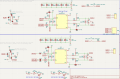
I am working with an RS485-based sensor communication system. My PCB has two separate RS485 transceiver ICs, each with an independent communication bus:

  • RS485 IC U8 → A/D1+ and B/D1− bus
  • RS485 IC U10 → A/D2+ and B/D2− bus
The issue occurs only with U8 and the A/D1+, B/D1− bus.

For the U8 bus, communication works properly when the 120 Ω termination resistors are removed from both ends. However, when I add a 120 Ω termination resistor at either the sensor end or the zonal-controller end, communication stops. When 120 Ω termination is added at both ends, communication also fails.

Measured differential voltage between A/D1+ and B/D1−:

  • No termination: ~4.3 V
  • 120 Ω at one end: ~286 mV
  • 120 Ω at both ends: ~160 mV
However, the U10 bus (A/D2+, B/D2−) works correctly under all these conditions. Communication is successful with no termination, with 120 Ω termination at one end, and with 120 Ω termination at both ends.

Therefore, the problem appears to be specific to RS485 transceiver U8 or its associated A/D1+, B/D1− bus circuitry, rather than the sensor, cable, or communication protocol.

Questions
  1. Why does adding a 120 Ω termination resistor cause communication failure only on U8 / A/D1+, B/D1−?
  2. Is the ~160 mV differential voltage with two 120 Ω terminators normal?
  3. Could the issue be related to the U8 transceiver's drive capability, biasing resistors, PCB layout, or surrounding components?
  4. Since U10 / A/D2+, B/D2− works correctly under the same conditions, what differences should I check between the U8 and U10 circuits?
  5. What measurements should I perform to identify the root cause?
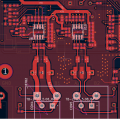
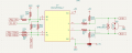
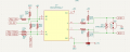
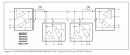
I have attached the RS485 schematic and PCB layout for reference.

  • Images 5 and 6 show the zonal-controller side, where the zonal controller sends a request to the sensor and waits for the sensor response.
image (5).pngimage (6).png
  • Image 4 shows the sensor-node side, where the sensor receives the request and then sends the response data back to the zonal controller.
image (4).png

Key observation: The U10 bus works with or without termination, while the U8 bus fails when even a single 120 Ω termination resistor is added.
 

cmartinez

Joined Jan 17, 2007
8,841
  1. RS485 signals are differential, therefore there is no need for biasing pull-up or pull-down resistors at the A/B lines. In fact, they may be detrimental. I suggest you remove them.
  2. The TVS diode you're using for protection is of the bidirectional type and it should work. But I don't know if said diode adds capacitance to the line and is affecting communication or not. You could remove them for testing purposes
  3. Same thing with the gas discharge tube. Remove them for testing purposes.
 

Thread Starter

akash.kumar123

Joined Jul 20, 2026
12
  1. RS485 signals are differential, therefore there is no need for biasing pull-up or pull-down resistors at the A/B lines. In fact, they may be detrimental. I suggest you remove them.
  2. The TVS diode you're using for protection is of the bidirectional type and it should work. But I don't know if said diode adds capacitance to the line and is affecting communication or not. You could remove them for testing purposes
  3. Same thing with the gas discharge tube. Remove them for testing purposes.
Hello CMartinez, first I would like to understand why one circuit works with the 120 Ω termination resistor while the other does not, even though both circuits appear to have the same design and components.
 

cmartinez

Joined Jan 17, 2007
8,841
Hello CMartinez, first I would like to understand why one circuit works with the 120 Ω termination resistor while the other does not, even though both circuits appear to have the same design and components.
If that's the case, it could be for one of two possible reasons that I can think of:
  1. Differences in circuit layout at the pcb
  2. Your arrangement (i.e. the biasing resistors) has pushed the rs485 chips to its limits, making them unstable. In those conditions the chips are working at a threshold and may or may not work.

Of the two possibilities mentioned above, I think the second one is the most likely.
 

MisterBill2

Joined Jan 23, 2018
28,065
When an impedance (source impedance) or thansmission line impedance is given, that is not usually the recommended line termination resistor value!!
How many RF receiver circuits have you seen with 50 ohm resistors across the input?? How many RF Transmitters?? Probably none, ever!! Circuit impedance is seldom a resistor!
 

0ri0n

Joined Jan 7, 2025
184
Where is the third wire for the bus? How are the sensors powered? Terminations go on both ends, fail-safe resistors only on one end of the bus. TVS diodes are bidirectional but schematic shows otherwise. What is JP10/17 for?
 

ThePanMan

Joined Mar 13, 2020
950
Since I know little to nothing about this issue what I have to offer may be worth little to nothing. Nevertheless, I DO have a question for consideration: Are the sensor wires the same length? Same type? You could be seeing cross talk between one set of sensor wires that could be triggering the error. I remember years ago installing a burglar alarm in a customers home. Her complaint was every time she activated the system the panel would go into Panic Alarm. Every time we went out to investigate we could not replicate the same problem. So we tried replacing the control panel wiring thinking there could be a possible break and short within the first cable. That changed nothing. We tested the panel for several days, switching the system on and off but could never get it to trigger the panic mode. One of the engineers suggested it could be cross talk between the lines. So we ran a separate set of wires for the panic and the customer never had another issue with panic triggering unless she wanted it to.

I think the issue MIGHT be with your wiring. But what do I know?!
 

panic mode

Joined Oct 10, 2011
5,189
1787330165544.png
why not stick with circuits shown in the datasheet?

remove R26, R36, JP4 etc. the only resistors on bus side are the termination resistors and they need to be placed at the ends of the bus. also for best results, bus need to be shielded and shield has to be grounded.

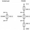
btw. there are many 485 based bus types. some of them do use biasing resistors inside terminator (like your R26, R36 in image above). an example of this is ProfiBus and the values of those pull resistors are 390 Ohm but then the center resistor value is 220Ohm instead of 120 Ohm.

1787331197696.png

but - ProfiBus has own variant of transceiver ICs that are designed to work with this. you are using MAX485 so stick with circuit for MAX485:

1787330820782.png
 
Last edited:

Rf300

Joined Apr 18, 2025
119
What is the line length and the transmission speed of the RS485 bus? At higher transmission speeds or more line length, the TVS diodes between the differential pair will cause problems. Each diode has a junction capacitance of 0.7 nF for the bi-directional or 1 nF for the unipolar type. This will cause signal distortion due to slow rising signal edges.

Furthermore a TVS at this place and with 36 V is absolutely useless. The clamping voltage is somewhere between 40 and 44V and it would only clamp the differential voltage between the signal lines. For a properly installed transmission line, this is almost impossible. So simply remove all your TVS's. Whether an RS485 interface needs some protection depends on the specific use case (cable length, EMC conditions, voltage differences, ...) and has to be decided individually.

The differential voltage you measured is typical for a system with disabled drivers. Usually RS485 receivers accept any voltage difference > 0 V as a logical "1", although most RS485-transceiver datasheets sppecify the receiver output level as "undefined" for an input voltage difference between +0.2 V and -0.2 V. Unless you have several 100 m of cable, the differential voltage with an enabled driver should be well over 1 V measured at the far end of the cable. Do you have oscilloscope screenshots of the signals at the transmitter and receiver while enabling the driver and sending data?
 

Rf300

Joined Apr 18, 2025
119
an example of this is ProfiBus and the values of those pull resistors are 390 Ohm but then the center resistor value is 220Ohm instead of 120 Ohm.
These values form a termination resistance of 172 Ohm (220 || 2*390) which fits quite well to the caracteristic impedance of a little bit more than 160 Ohms of the Profibus cable. This higher impedance is caused by the lower capacitance of the Profibus cable compared to a standard CAT3 cable. Additionally, this termination provides a bias voltage of 1.1 V in idle state of the bus to increase noise immunity in industrial environment.

ProfiBus has own variant of transceiver ICs that are designed to work with this.
There was no special transceiver for Profibus, but some of the standard RS485 transceivers were more robust than others, so those were preferred for Profibus. But Profibus will work with any standard RS485 transceiver.
 

panic mode

Joined Oct 10, 2011
5,189
yes... but that also means creating bottlenecks. entire network is only as fast as slowest node. and at the time when most fieldbus networks (DH, DH+,DeviceNet, CompoBus...) were limping at some 100-500kbps, Profibus was zipping at speeds up to 1.5Mbps, and then 12Mbps. while Profibus supported many baud rates (and very slow ones, for long range communication), i think it was tight specs and certification/compliance issue that let to marketing transceivers as ProfiBus...
 
If the RS485 functions correctly without that 120 ohms terminating resistor, WHAT IS THE ADVANTAGE anticipated from adding the 120 ohm resistors?? THAT ismy big question.
 
My first comment for this post.

1) Possible issues for higher baud rates - capacitance of your TVS diode is meant for power supply rails, this TVS has hundreds of pF of capacitance. Also, schematic symbol for your TVS diode should have bidirectional symbol shape. https://upload.wikimedia.org/wikipe...e_symbols.svg/330px-TVS_diode_symbols.svg.png

2) Possible issues with not connecting signal ground between RS485 nodes.

3) Possible RS485 impedance mismatch issues, since you didn't state the type of cable or wiring, or its impedance.
 
Top