Other than LM339 or LM393 you suggested, are there any other than is better at high frequency than those because I would like to buy a good comparator?
Something else you may want to consider is just an off the shelf crystal oscillator. These are available from a wide range of manufacturers and distributors. Dale Vishay comes to mind but other manufacturers also make them. This all depends on the accuracy and stability you want or need but you get everything in a single small package and they can also be gated. The link is to a 1.0 MHz version which can easily be divided down using for example an old 7490 or any common divide by ten decade counter divider. This will afford you a nice clean accurate square wave which is very stable. The entire oscillator part is typically well below $5.00 USD. These are pretty much universally available and very inexpensive. You also get a nice symmetrical square wave.
Look it up, the lM741 opamp design is 53 years old and its datasheet shows that it has trouble producing an output above 9kHz.
For a 100khz squarewave you need a circuit that produces at least 1MHz but 2MHz will be better.
Wrong.
Comparators do not have the internal compensation needed for stable operation in such circuits.
Op amps do (which slows them down when you try to use them as comparators).
Hi sir, I saw this oscillator in the datasheet. Would this be good at producing 100kHz and can the negative rail voltage supply be a positive value that is less than the positive rail voltage ? This is because I tested the LM 741 with a positive supply voltage at its negative rail, it does not work
Yes, those run at over 100 kHz if you use a fast enough comparator. I am using an LM319 to get upwards of 1 MHz with a similar oscillator. The LM393 might also work at 100 kHz.
Yes, those run at over 100 kHz if you use a fast enough comparator. I am using an LM319 to get upwards of 1 MHz with a similar oscillator. The LM393 might also work at 100 kHz.
Yes, those run at over 100 kHz if you use a fast enough comparator. I am using an LM319 to get upwards of 1 MHz with a similar oscillator. The LM393 might also work at 100 kHz.
Hi, thats awesome. So, the arrangement of components is the same as the circuit diagram above for LM 319 that you used right? Planning to buy LM 319 to produce this high frequency square wave. This LM 319 has 14pins right and can the negative rail be a negative voltage so that it can produce a (10V to -10V square wave) that oscillate about origin?
The 741 opamp was designed 53 years ago to use a power supply that is 30V. Most will not work if their supply is less than 10V. The 741 opamp has trouble (poor slew rate) above 9kHz.
If you use a negative rail voltage that is a positive value that is less than the positive supply voltage then their difference is the total supply which must be enough for the IC and then you are messing up the bias voltage that is supposed to be half the total supply voltage.
The opamp circuit in the first post has a dual supply with the ground (the opamp bias voltage) of the circuit at half the supply voltage.
The comparator circuit has a single positive supply and ground. It is also biased at half the supply voltage.
Hi, thats awesome. So, the arrangement of components is the same as the circuit diagram above for LM 319 that you used right? Planning to buy LM 319 to produce this high frequency square wave. This LM 319 has 14pins right and can the negative rail be a negative voltage so that it can produce a (10V to -10V square wave) that oscillate about origin?
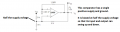
This (above) is the circuit I and others used. It is similar but this one uses and LC tank (C1 and Lx) connected to the non-inverting input of the LM319.
The LM319 is good for 36 volts so ±10 volts should be fine. If you use a split supply you will not need the resistor from (in the schematic above) +5V to the + input.
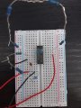
I am using an LM 319 High Speed Comparator to produce high frequency square wave as shown. However, from the first diagram, I assembled the connections based on second diagram, it does not work. The V+ and V- that is negative rail and positive rail I used is +9 and -9 V from 2
battery. Any suggestions how to make it work using LM 319 High Speed Comparator?
Each comparator is open-collector and needs a pull-up resistor (say 10k) to the +9V supply rail.
The inputs of the unused comparator should not be left floating. Connect them to ground.
Each comparator is open-collector and needs a pull-up resistor (say 10k) to the +9V supply rail.
The inputs of the unused comparator should not be left floating. Connect them to ground or 9V.
 Facebook
 Google
 GitHub
 Linkedin

") , I saw this oscillator in the datasheet. Would this be good at producing 100kHz and can the negative rail voltage supply be a positive value that is less than the positive rail voltage ? This is because I tested the LM 741 with a positive supply voltage at its negative rail, it does not work
, I saw this oscillator in the datasheet. Would this be good at producing 100kHz and can the negative rail voltage supply be a positive value that is less than the positive rail voltage ? This is because I tested the LM 741 with a positive supply voltage at its negative rail, it does not work